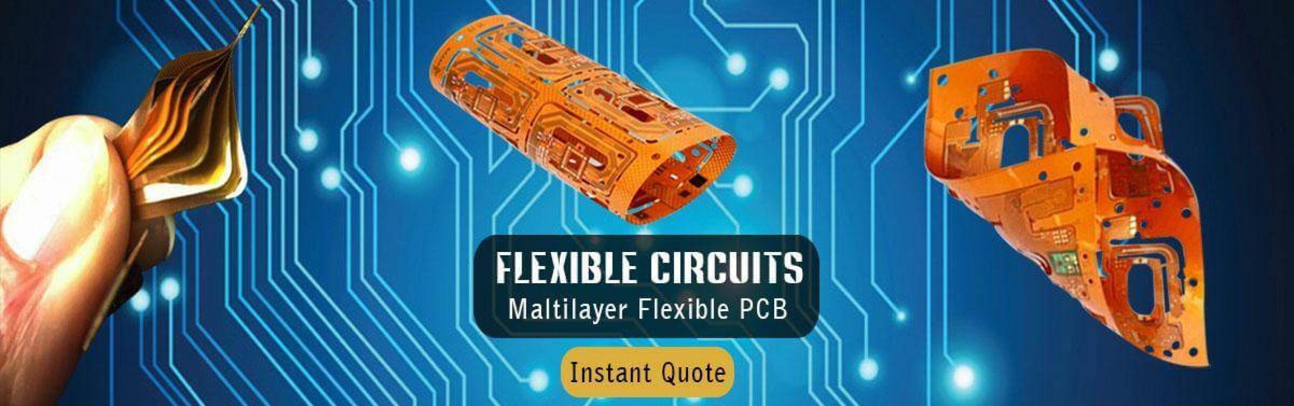
Flexible PCB
Flexible printed circuits offer a broad array of physical and electrical interconnect solutions that cannot be achieved with rigid printed circuit board solutions. At Hemeixinpcb, we offer a comprehensive range of flexible circuit manufacturing and circuit board assembly.
A flexible printed circuit board (FPC or FPCB) is a printed circuit board having a base material composed of polyester resin or polyimide resin. The flexible printed circuit board can be variously bent and folded according to the manufacturing needs of any particular application.
The basic portion of a rigid flexible PCB is a film, which is used to support circuits composed of copper pieces. The various flexible pcb manufacturing process properties belonging to a flexible printed circuit board include: lightness, soft, thinness, smallness, ductility, flexibility, and high-wiring density. Accordingly, the flexible printed circuit board offers design freedom in electronic equipment, and in particular, saves an amount of wasted space, thereby downsizing the equipment. Therefore, the rigid flexible PCB is typically applied within tiny products, such as notebooks, mobile phones, personal digital assistants (PDAs) and information appliances (IA)
We offer kapton flexible pcb including :
- Single or double-sided circuitry, sculptured flex PCB circuits
- Adhesive-based and adhesiveless constructions
- Surface finishes include anti-tarnish, immersion silver, tin, solder, electroplated nickel/gold, and ENIG
- Film stiffeners/ Polyimide Stiffeners
- EMI shielding
- Stainless steel stiffeners
- Aluminum Stiffeners
- No MOQ/MOV prototype
- Large format flexible circuit
Special offer pyralux flexible pcb including :
- Sculptured flexible PCB
- Heavy copper flexible circuits, copper weight can be up to 10 OZ.
- Polyimide flexible heaters
- Kapton polyimide heaters
- Long flexible circuit boards up to 2100mm
- HDI flex PCB
- Turnkey flex PCB
- COB flex PCB
- Wire bonding flex PCB
- Quick turn flexible PCB
What is Flexible PCB
Flexible printed circuits, also known as flex circuits, are sometimes regarded as a printed circuit board (PCB) that can bend, when in reality there are significant differences between PCB’s and flex circuits when it comes to design, fabrication and functionality. One common mistake that designers make is to design a flexible circuit using the same rules as a PCB. Flex circuits require a unique set-up and have their own set of design rules that the Hemeixin team has termed “flex-izing” and have worked hard to perfect over the last many years.
Flexible PCB, which also called Flex PCB, Flexible circuit board or flex circuit, it consists of PI base material, adhesive layer, copper layer, coverlay and sometimes with stiffeners. Flexible PCBs are now being used widely to replace traditional FR4 PCB in various different applications due to the benefits from flex PCB specially. Although more expensive than a normal rigid PCB, the right design in the right application could save weight and time in assembly, coupled with the reliability which makes flexible circuit board a worthwhile consideration.
A flexible printed circuit consists of a metallic layer of traces, usually copper, bonded to a dielectric layer, usually polyimide. Thickness of the metal layer can be very thin (<.0001″) to very thick (> .010″) and the dielectric thickness can vary from .0005″ to .010″. Often an adhesive is used to bond the metal to the substrate, but other types of bonding such as vapor deposition can be used to attach the metal.
Because copper tends to readily oxidize, the exposed surfaces are often covered with a protective layer, gold or solder are the two most common materials because of their conductivity and environmental durability. For non-contact areas a dielectric material is used to protect the circuitry from oxidation or electrical shorting.
The number of material combinations that could go into a flexible printed circuit are nearly endless; current, capacitance, chemical and mechanical resistance, temperature extremes and type of flexing are just some of the criteria that impacts the material selections that best meet the functional needs. An experienced All Flex pcb design engineer takes the critical requirements into consideration when designing a circuit to meet your needs.
Flexible printed circuit boards (FPC) has become a common component of electronic products due to its lightness and flexibility performance. It is widely used in smart terminal, wearable electronics, consumer, automotive, industrial and medical fields. The miniaturization and integrated function of electronics product development is driving FPC to fine line and multilayer design.
Flexible PCB Applications
flex circuits are used widely in everyday technology and electronics in addition to high-end, complex completed components. A few of the most prominent examples of flexible circuits usage is in modern portable electronics, devices, hard disk drives and desktop printers.
Flexible PCB are also used extensively in other applications and industries including:
- Communications
- Consumer Electronics
- Automotive
- Medical
- Industrial
- Aerospace
- Military
- Transportation
In transportation they are extensively used due to their improved resistance to vibrations and movement.
Basic Types of Flexible PCB
Flexible circuit applications typically include designs where the circuit wraps around other electrical subsystems or rests against the inside of an instrument enclosure. Therefore, the material options commonly available for these purposes have specific mechanical, thermal and chemical properties. So, it’s possible to adapt this layer depending on the desired performances (mechanical strength, temperature resistance, bending…).
- Single sided flexible PCB
- Double sided flexible PCB
- Multi layer flexible PCB
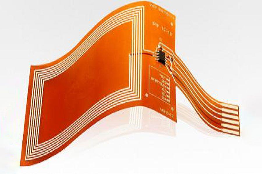
Single sided flexible PCB
- IPC 6013 - Type 1
- Description:
One conductive copper layer bonded between two insulating polyimide layers
Example construction: coverlay/copper/flex core - Configurations:
Single-sided access, dual-sided access, unsupported fingers - Flex Core Materials:
Standard thicknesses: 1/2 mil to 3 mil in either adhesive or adhesiveless constructions
Standard copper thicknesses: 1/3 oz to 2 oz in rolled annealed or electro deposited formats - Coverlays:
Standard thickness: 1/2 mil to 2 mil polyimide, with 1/2 mil to 2 mil epoxy or acrylic adhesive - Stiffeners:
Component support or ZIF connector thickness requirments
Materials: polyimide, FR4, stainless steel, aluminum - PSA (pressure sensitive adhesives) available for attachment purposes
- EMI/RF shielding films available
- Applications:
Suitable for either bend to fit or dynamic flex applications

Double sided flexible PCB
- IPC 6013 - Type 2
- Description:
Two conductive copper layers with an insulating polyimide between and external polyimide insultaing layers
Plated through-holes provide circuit connection between layers
Example construction: coverlay/copper/flex core/copper/coverlay - Configurations:
Single-sided access, two-sided access, castelated holes - Flex Core Materials:
Standard thicknesses: 1/2 mil to 4 mil in either adhesive or adhesiveless contructions
Standard copper thicknesses: 1/3 oz to 2 oz in rolled annealed or electro deposited formats - Coverlays:
Standard thickness: 1/2 mil to 2 mil polyimide with 1/2 mil to 2 mil epoxy or acrylic adhesive - Stiffeners:
Component support or ZIF connector thickness requirments
Materials: polyimide, FR4, stainless steel, aluminum - PSA (pressure sensitive adhesives) available for attachment purposes
- EMI/RF shielding films available
- Applications:
Bend to fit and dynamic flex applications (construction dependant)
High-speed controlled impedance in surface micro strip configuration

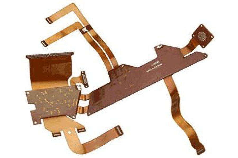
Multi-Layer Flexible PCB
- IPC 6013 - Type 3
- Description:
Three or more flexible conductive layers with flexible insulating layers between each one and external polyimide insulating layers
Plated through-holes provide circuit connection between layers
Example construction: coverlay/copper/flex core/copper/adhesive/flex core/copper/coverlay - Configurations:
Single-sided access, two-sided access, castelated holes - Flex Core Materials:
Standard thicknesses: 1/2 mil to 4 mil in either adhesive or adhesiveless contructions
Standard copper thicknesses: 1/3 oz to 2 oz in rolled annealed or electro deposited formats - Coverlays:
Standard thickness: 1/2 mil to 2 mil polyimide with 1/2 mil to 2 mil epoxy or acrylic adhesive - Stiffeners:
Component support or ZIF connector thickness requirments
Materials: polyimide, FR4, stainless steel, aluminum - PSA (pressure sensitive adhesives) available for attachment purposes
- EMI/RF shielding films available
Applications:
Bend to fit only
High-speed controlled impedance in surface micro strip or stripline configurations

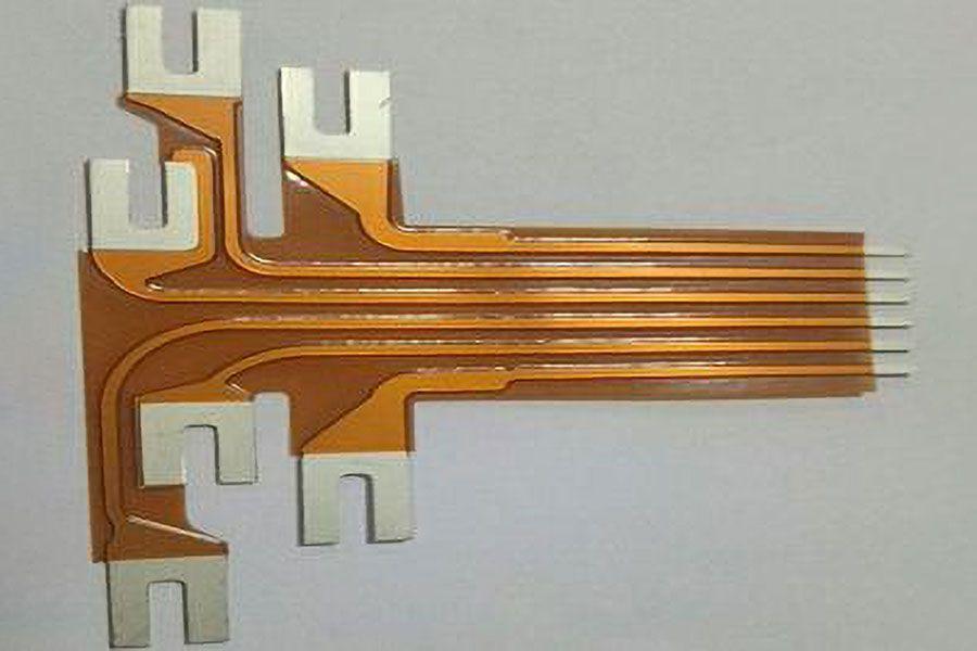
FLEX CIRCUIT STIFFENERS
When it comes to flex circuits and rigid-flex PCBs, stiffeners are a common and important requirement in many designs as they improve the durability and reliability of the flex circuit in many applications.
Stiffeners also provide a mechanical function for the flexible area and are not part of the electrical requirements of the overall part. If your board requires stiffeners on one or both sides of the flex, it may require multiple lamination cycles, which will add to the cost and the lead time. However, there are certain cases where stiffeners are ultimately required.
Flexible PCB Stiffener Requirements
Flexible PCB stiffener requirements fall under the following usage categories:
- Rigidizing connector areas for stress relief of larger connectors or repeated insertions of the connector
- ZIF (Zero Insertion Force) Thickness Requirements
- Localized Bend Constraint(s)
- Creating a flat surface for the placement of SMT pads and components
- Minimizing component stress
- Managing heat dissipation (aluminum and steel)
- Make the array rigid enough to run through the automated assembly processes without a fixture
Why Use Stiffeners in Flex Circuit Application
Flexible PCB stiffener requirements fall in the following usage categories:
- Rigidizing Component / Connector areas
- ZIF (Zero Insertion Force) Thickness Requirements
- Localized Bend Constraint(s)
Component / Connector Stiffeners
Function:
- Creates a localized rigid area where components / connectors are attached.
- Protects solder joints by preventing bending of the flex in component area.
Material Options:
- FR4, Polyimide, Aluminum, Stainless Steel
- Variety of thicknesses available
- Attachment methods:
- Thermally bonded with flex adhesive
- Pressure Sensitive Adhesive (PSA)
ZIF Stiffeners
Function:
- Localized thickness increase at contact fingers to meet specific ZIF connector specifications.
Material Options:
- Polyimide Only
- Variety of thicknesses available to meet specific design requirements
- Attachment methods:
- Thermally Bonded with flex adhesive only
Localized Bend Constraints
Function:
- Restrict bend area(s) to specific location(s) in a flex pcb design to either facilitate final assembly, achieve specific bend requirement(s) or other end use requirement.
Material Options:
- FR4, Polyimide
- Variety of thicknesses available
- Attachment methods:
- Thermally Bonded with flex adhesive
- Pressure Sensitive Adhesive (PSA)
Flex Circuit
- Single-layer, double-layer, multilayer and rigid-flex circuits with high layer counts to meet your interconnection needs
- Fine lines, circuit forming and selective bonding add to space and weight savings
- Stiffeners, pins, connectors and full turnkey electronics packaging for efficient integration into your application
- Inductive communication coils can be integrated with flex circuits to provide critical communication assemblies
Flexible Circuits Fabrication
There are two basic categories of processes for manufacturing a flexible printed circuit: Subtractive and additive.
In a subtractive process, one starts with a solid area of metal, and the unwanted areas of metal are removed to form the traces. Screen printing and photo imaging are the two most common processes used for defining the circuitry pattern.
In an additive process, one starts with a bare dielectric layer and the metallic traces are added only where needed to form the circuit. The conductive layer can be printed, plated, or deposited in a variety of manners.
The subtractive processes are more common because they are more robust and cost effective, and they allow greater choices in final product configuration. The flexible circuit boards created by the additive process have less current-carrying capability and environmental resistance than circuits created by the subtractive processes.
Flexible Circuits manufacturing process
After taking the time to compose the perfect flex circuit design through the use of concurrent engineering, our team uses cutting-edge tools and technology to bring the drawing board to life. Each custom flex circuit is meticulously manufactured and assembled to meet the stringent criteria required by the client’s application, as well as the design standards for flex and rigid-flex circuits set by IPC 2223 and the qualification and performance specifications for flex and rigid-flex circuits set by IPC 6013.
Concurrent engineering is the key to successful flex fabrication. It allows us to clearly identify our client’s needs, develop a framework for success, and integrate our existing processes with our newfound knowledge to optimize the workflow management. We couldn’t achieve a smooth flex circuit manufacturing process by any other means!
Signal Integrity
Designing flexible circuits with ideal signal integrity is no easy feat, but the veteran engineers at Hemeixin. continuously produce groundbreaking designs that seek to eliminate many signal integrity challenges. We target the following factors to reduce or altogether eliminate signal interferences.
Our flexible circuits seamlessly integrate into your applications and deliver flawless performance even under stressful conditions, such as high-frequency and high-speed environments.
High Layer Count
Historically, high layer count flexible circuits are infamous for producing an array of technical challenges that have forced even the brightest minds to return back to the drawing board time and again. The beauty of the flexible circuit lies in its lightweight and compact design, which delivers the necessary power without the extra weight. Stacking more and more layers upon a flexible circuit increases the system’s complexity and depreciates its flexibility. It takes a talented group of individuals to assemble a high layer count flexible circuit without sacrificing flexibility or performance.
Minimum Bend Radius
Although flexible circuits were pioneered to eliminate the shortcomings of traditional rigid printed circuit boards, these innovative devices have their own guidelines and regulations, one of them being the minimum bend radius. Simply put, this is the minimum angle at which the flex board can bend. The minimum bend radius plays a huge role in reducing the risk of damage and it is a key performance indicator.
We strongly recommend evaluating the minimum bend radius of your flexible circuit before we enter the assembly process.
Printed Flexible Circuit
A flexible printed circuit board features a combination of several printed circuits as well as components that are positioned on a flexible substrate. These circuit boards are also known as flex circuit boards, flex PCBs, flex circuits, or flexible printed circuits. These printed circuit boards are designed using the same components as rigid printed circuit boards.
Copper is the most common conductor material used for making flexible PCBs. Their thickness may range from .0007ʺ to 0.0028ʺ. At Hemeixin, we can also create boards with conductors such as aluminum, Electrodeposited (ED) copper, Rolled Annealed (RA) copper, Constantan, Inconel, silver ink, and more.
Being one of the most experienced flex circuit board manufacturers, we are the first choice when clients conceptualize their complex flex circuit board designs. We can create circuit boards in different flexible substrate materials including polyimide, polyester, Polyethylene Naphthalate (PEN), Polyethylene Terephthalate (PET), and more. In addition to these, we can also provide these boards in any preferred material finishes including leaded or lead-free soldering, tin, immersion nickel/gold, hard nickel/gold, wire bondable gold, silver, carbon, and many more. The choice of the material finish will entirely depend on customers’ application requirements. For instance, tin finishing is perfect for covering exposed pads on the flex circuits, whereas soft gold covering will be ideal for covering when assembly process such as wire bonding is being performed.
With a large number of investments on the facilities of flexible printed circuit board and continuously innovating the flexible circuit board manufacturing technology, Hemeixin is able to manufacture flexible PCBs with a great variety of technologies, from simple single sided flex PCB, double sided flex PCB to complex multilayer flexible PCB, and support prototype FPC with laser cutting & flying probe test to mass production with toolings.


