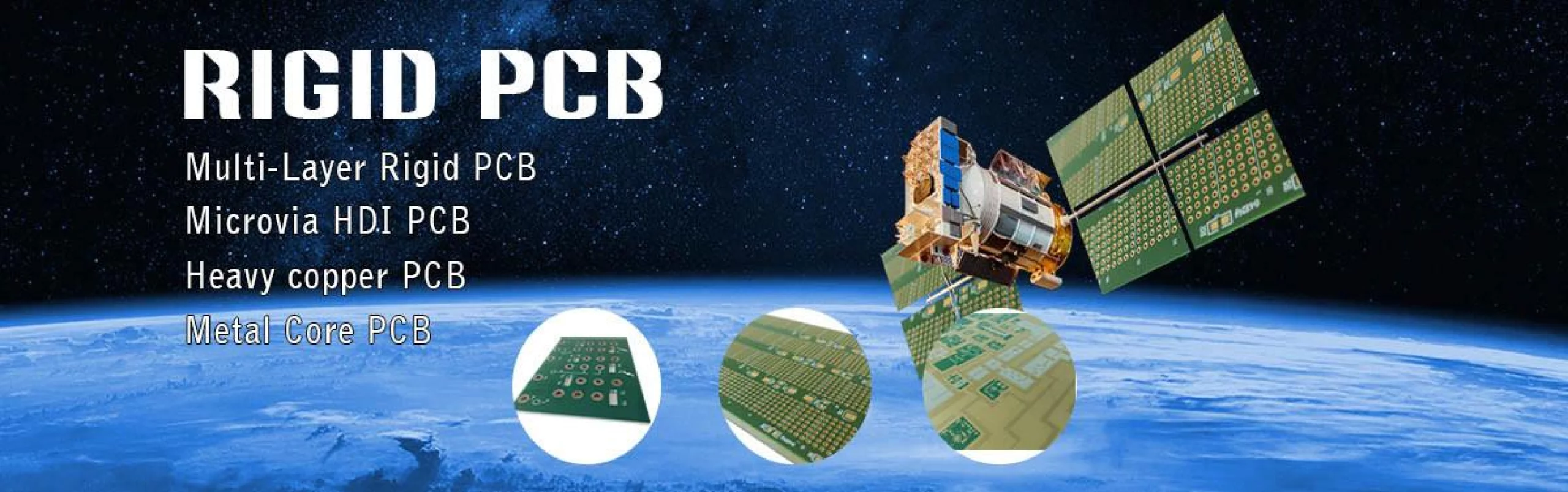
IC Substrate
IC substrates represent the highest level of miniaturization in PCB manufacturing and shares many similarities with semiconductor manufacturing. Flip Chip technology is the foundation for packaging high performance Integrated Circuits used in applications from consumer-level smartphones, tablets and PCs to high-performance graphics workstations, servers and IT infrastructure equipment. IC substrates serve as the connection between the IC chip(s) and the PCB through a conductive network of traces and holes.
Advanced technology that is shaping the future. Hemeixinpcb produces many types of IC substrates on which IC chip(s) are attached to the IC substrate utilizing wire bonding and, or flip-chip methods. Our IC substrates that Hemeixinpcb manufacturers include:
- CSP (Chip Scale Packages)
- FC-CSP (Flip Chip) CSP
- BOC (Board on Chip)
- PoP (Package on Package)
- PiP (Package in Package)
- SiP (System in Package)
- RF Module
- LED Package
IC substrates Capabilities:
- Layer count : 1L / 2L / 3L / 4L , up to 22 layers.
- Minimum line width and spacing: 9/9 µm
- Minimum laser via/pad: 45/95 µm
- Impedance control for critical signal traces
- RoHS compliance materials
- Bump pad: minimum 130 µm bump pitch
- Structure: any layer, coreless, cavity, embedded passive, Embedded trace (down to 20 um pitch)
- Wide material and surface finish options available
- Thickness: 100 um (1.5L) ~ 225 um (5L)
- Smallest Package Size: 3 x 3 mm up to 15 x 15 mm
Ic Substrate Applications:
- Hand-held, Mobile, Networking
- Smart phone, Consumer electronics and DTV
- CPU, GPU and Chipset for PC application
- CPU, GPU for Game Console (eg. X-Box, PS3, Wii…)
- DTV Chip Controller, Blu-Ray Chip Controller
- Infrastructure application (eg. Network, Base Station…)
- ASICs
- Digital Baseband
- Power Management
- Graphic Processor
- Multimedia Controller
- Application Processor
- Memory card for 3C products (eg. Mobile/DSC/PDA/GPS/Pocket PC/NoteBook)
- High Performance CPU
- GPU, ASIC Devices
- Desktop / Server
- Networking
- Game Console
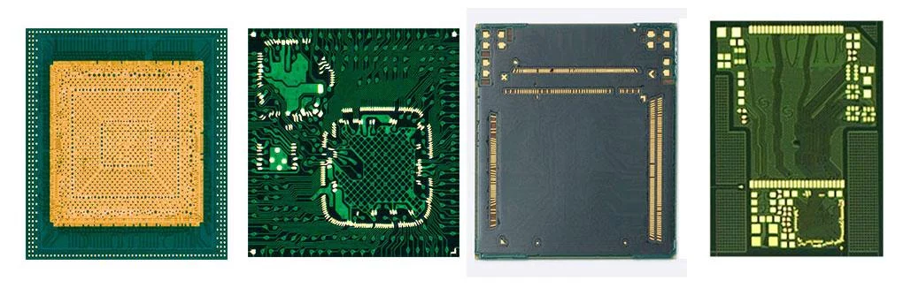
Flip Chip Package Substrate solutions
The product is a package substrate that is used for the core semiconductors of mobile devices and PCs. It transmits electric signals between semiconductors and the main board, and protects expensive semiconductors from external stress. Compared with general substrates, as this substrate is a high-density circuit substrate containing more microcircuits, the assembly defects and incurred costs in directly bonding expensive semiconductors to the substrate can be reduced.
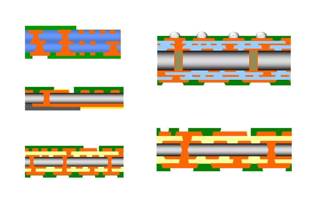
Flip Chip Package Substrate Types
Integrated circuit (IC) packaging board (IC Substrate) is the core component of integrated circuit packaging. It is a direct carrier for semiconductor grains (DIE) and various passive devices (Passives). It is also a key material for advanced packaging. The packaging board provides the functions of telecommunications interconnection, performance improvement, fixed support, heat dissipation and isolation protection for semiconductor grains with various passive devices. The function is the basis for realizing the thin, miniaturized, high density and high performance of integrated circuit packaging.
SiP Package Substrate
SiP (System in Package) refers to the semiconductor module that integrates multiple semiconductor chips and passives in one package to achieve system-level electrical performance.
SiP Package Substrate Features
- 1.5~12 layers, odd or even layer substrates, ultra-thin substrate stack-up
- Via Post or Copper pillar is a sequential build-up substrate plating process which can be started and interconnected at any layer
- Large Copper block structures can be plated within the substrate to reduce IR drop and improve power integrity
- Compatible with traditional Tenting/MSAP technology
- Using via post or copper pillar instead of laser via to realize high-density interconnection of any layer and any shape
- The consistency of copper pillar interconnection can improve the performance of RF package and ensure signal integrity
- Stacked bar-shape copper pillars or plated heat spreaders create a three-dimensional connection channel for efficient heat dissipation for the chip
Embedded Package Substrate/Module
A new type of packaging method in which the chip or passive components are embedded between the metal layers inside the substrate, and the I/O of the chip or device are fan-out to the external pin through the micro-vias and metal layers. This chip embedded substrate allows surface area on top to place additional chips and passives devices on the top surface to gain higher integrated level of functionality in 3D stack-up. By using this innovated and customized process, all the components can be integrated in one packaged to form a new system-level package or module.
Embedded Package Substrate Features
- The chip embedded substrate can support 1~5 fanout layers, and realize a 3D integrated structure
- Seamless connection between chip and carrier board using wafer-like process with thin film Sputtering Ti/Cu (Sputter Ti/Cu)
- Flexible advanced design rules can achieve thinner and smaller formfactor devices than the traditional semiconductor package
- Manufactured using Hemeixin independent intellectual property (IP), and compatible with traditional MSAP process, that allows extensive chip and passive component integration
- The connection between the chip and the substrate is formed through Sputtering a seed layer of thin metal film (Ti/Cu) in the wafer-like process, which significantly improves the electrical performance and heat dissipation
- effect, as well as the long-term reliability
- The process is a Panel Level Fanout that can achieve lower cost structures than current packages processed using Wire bond, or Flip Chip technologies
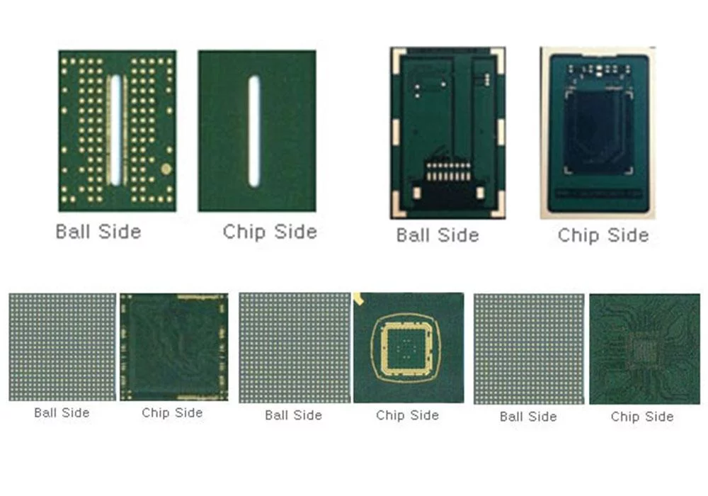
CSP (Wire Bond Chip Scale Package) Substrate
CSP(Chip Size Package) is a product whose package substrate size does not exceed 120% of the semiconductor chip size. To reduce the area size, the CSP with highly dense wiring compared to general BGA is formed. The most important goal of CSP is to reduce the mounting area size.
Chip Scale Packaging (CSP) utilizes fine pattern technology, very small via's, ultra thin copper foil and build up structure for high density designs and flexibility. The CSP substrate provides high reliability in both connection and isolation.
CSP Package Substrate Application
- Memory, analog, ASICs, Logic, RF devices,
- Notebook, Subnotebook, Personal Computers,
- GPS, PDA, wireless telecommunication system
CSP Package Substrate Features
- Fine patterning technology for high density design
- Build up structure for high design flexibility
- High reliability in connection and isolation
- Adoption of low CTE material suitable for PoP
WBCSP(Wire Bonding Chip Scale Package) Package Substrate
This is a semiconductor chip the size of which is more than 80% of that of the finished part. It is called WBCSP (Wire Bonding CSP) because a gold wire bonding method is applied to connect the semiconductor chip and the PCB. A gold wire is used to connect the chip and PCB, and multi-packaging is possible, which makes the product mainly applicable for memory chips. In particular, UTCSP (Ultra Thin CSP) products are made with a thickness of 0.13mm or thinner. With a high degree of freedom in the chip to PCB connection, multi-chip packaging is made possible, and better performance is realized compared with other products of the same thickness.
RF Modules (Radio Frequency) Substrate
Higher demand on frequency bandwidth, driven by massive apps and multi media through wireless telecommunication, needs more bands in the handset. Migrating into advanced telecommunication protocol and carrier aggregation both drive the demand on numbers of band, also power amplifiers and front end modules. RF module is the analog circuit which is different from digital ones. It requires much more skill on circuit/pattern design and component manufacturing.
RF modules Substrate Features
- Strip form
- Thick copper
- Impedance control
- Strict uniformity control
PBGA (Plastic Ball Grid Array) Package Substrate
PBGA(Plastic Ball Grid Array) expresses the structural characteristics of the Package Substrate. In other words, on the back of the PCB, instead of leads, solder balls are lined up to connect the substrate to the main board. The term PBGA is used as generally as the Package Substrate.
The typical BGA substrate for wire bonding IC packaging application is based on glass fiber immersed resin copper clad laminate. PBGA packaging is a cost effective solution for wide range of chip I/O count. When IC functionality has been upgraded, it always migrates from lead frame packaging into BGA packaging.
PBGA Package Substrate Features
- Strip form
- Multiple surface finish
- Wide range of material selection
- Optimization of substrate design considering thermal and electrical performance
- Finer ball pitch and thinner package thickness
- High electrical performance due to short wire length
- Etch back process
- Available both for Flip-chip & Wire bonding
- High density wiring by Semi-additive process
- Fine pattern formation to bond on trace technology
- Substrate dimension stability to package on package
- Leadless plate design for interconnection
PBGA Package Substrate Application
- ASIC, DSP and Memory, Gate Arrays,
- Microprocessors / Controllers / Graphics
- PC Chipsets and Peripherals
- Graphics Processors
- Set-Top Boxes
- Game Consoles
- Gigabit Ethernet
FCCSP Package Substrate
CSP(Chip Size Package) is a product whose package substrate size does not exceed 120% of the semiconductor chip size. To reduce the area size, the CSP with highly dense wiring compared to general BGA is formed. The most important goal of CSP is to reduce the mounting area size.
This is called Flip Chip Chip Scale Package (FCCSP) as semiconductor chips are upturned and connected to a board through a bump rather than wire bonding. It is mainly used for the application processor (AP) chips of mobile IT devices. Also Compared to WBCSP using Gold Wire, the process using Flip Chip can be applied to high-density semiconductors because the route of electrical signals is shorter, and larger input and output can be accommodated.
FCCSP Package Substrate Features
- Single unit or strip form
- Fine pitch, mSAP process
- Thin and flat board
- Coreless process
FCCSP Package Substrate Application
- EEPROM. NAND Flash, power management, integrated passive networks, standard analog device
- PRAM, LPDDR,ONEDRAM, NAND Flash
- Mobile phone, PDAs, laptop PCs, disk drives, digital camera MP3 player, GPS navigation devices, potable product
Hemeixin’s Flip Chip CSP (fcCSP) package – a flip chip solution in a CSP package format. This package construction partners with all of our available bumping options (Copper Pillar, Pb-free solder, Eutectic), while enabling flip chip interconnect technology in area array and, when replacing standard wirebond interconnect, in a peripheral bump layout. The advantages of flip chip interconnect are multiple: it provides enhanced electrical performance over standard wirebond technology, it allows for a smaller form factor due to increased routing density, and it eliminates the z-height impact of wire-bond loops.
The fcCSP package is assembled on a laminate or mold-based substrate with or without a core. The package is processed in a strip format for manufacturing efficiency and to minimize cost and enables bare die, overmolded and exposed die structures. The thermal challenges of high-power devices can be managed by applying an integrated heat spreader. Antenna in Package (AiP) can be enabled with the use of bottom side chip attach. Finally, when coupled with copper pillar bumped die, fcCSP technology takes advantage of fine line/space substrate routing and bump pitch to reduce layer count and cost while increasing electrical performance.
The fcCSP package is an attractive option for applications in which both performance and form factor are critical. Examples include high- performance mobile devices (including 5G), infotainment and ADAS for automotive, and artificial intelligence. Further, the benefits from low inductance and increased routing density enable optimized electrical paths for high-frequency signals, making fcCSP suitable for Baseband, RF, and in-substrate antenna applications.
FCBGA Package Substrate
FCBGA (Flip-Chip Ball Grid Array), which is using the high-density micro bumps to connect the digital chips and substrate through the Flip Chip process, and place the passive devices next to the chips on the surface of substrate, to form BGA (Ball Grid Array) or LGA (Land Grid Array) package type. Hemeixin uses SAP (Semi-additive process) technology to manufacture the FCBGA substrate with high density and high layer counts to support the high-end flip chips, and make sure the high efficiency electrical interconnect and high-speed transmission.
FCBGA substrates are semiconductor packages with fine design rule and high reliability. Hemeixin provides IC packages with more than 3,000 I/Os, and which comply with next generation flip-chip LSI utilizing cutting-edge design rule and state-of-the-art processing technology.
The product is a high-integration package substrate that is used to connect a high-integration semiconductor chip to a main board. It is a highly-integrated package board that improves electrical and thermal characteristics by connecting the semiconductor chip and package board with Flip Chip Bump. In addition, the high integration of the CPU board circuitry requires an increase in the number of board layers and fine matching between layers; at the same time, the ability to manufacture thin boards for slimming sets is required.
FCBGA Package Substrate Features
- Leaders-in circuitization rule as line/space: 9µm/12µm
- Advanced small via formation with laser via technology
- Highly reliable thermosetting epoxy used
- Various surface finish options available (Ni/Au, SAC soldering, etc.)
- Applicable environmentally-friendly products (Halogen-free, Lead-free)
- 4~16 layers stack-up to realize the high-density interconnection requirement of advanced wafer process
- High precision, high density laser micro-via technology with superior alignment capability
- Ball Grid Array (BGA) or Land Grid Array (LGA) use this technology for connectivity to the die
- To utilize SAP process to bring high precision and high density of fine lines
- uBall technology is used to place up to tens of thousands of micro Sn balls on the top surface of the substrate. These Sn balls are used for connection with the micro bump on the flip chip die surface
Hemeixin Flip Chip BGA (FCBGA) packages are assembled around state‑of‑the‑art, single unit laminate or ceramic substrates. Utilizing multiple high density routing layers, laser drilled blind, buried and stacked vias, and ultra fine line/space metallization, FCBGA substrates have the highest routing density available. By combining flip chip interconnect with ultra advanced substrate technology, FCBGA packages can be electrically tuned for maximum electrical performance. Once the electrical function is defined, the design flexibility enabled by flip chip also allows for significant options in final package design. Hemeixin offers FCBGA packaging in a variety of product formats to fit a wide range of end application requirements.
BGA Package substrates process
What is semi additive process ?
Semi Additive Process (SAP) Technologies:
Electronic industry is rapidly moving towards finer pitches to accommodate higher speed required out of components. We have seen a migration from 1mm pitch to 0.8, 0.5, 0.4 and now 0.25mm pitches. At the same time the number of I/O required are increasing. We have started seeing increasing designs with sub 50µm (0.002”) line and spacing. Convention methods of forming traces are not going to be able to produce these circuit boards at a reasonable yield.
Benefits:
- Reduction in size and weight by 90% over current state-of-the-art in the China
- Effectively reduce layer count and lamination cycles
- Significant RF advantages over traditional subtractive etch processes
- Increased electronics density within a fixed area
Technical Papers:
- Material Reliability & Performance Study
- Stack Microvia Reliability
- Wrap Plating
- Trouble shooting Microvias
Conductor Patterning Technology to Enable Ultra-Fine Wiring
With a focus on SAP (Semi Additive Process), we provide the world-class micro patterning. We are also promoting the development of conductor patterning technologies of semiconductor revel toward future.
mSAP - modified Semi Additive Process
Miniaturization and new market requirements demand the development of innovative solutions in order to provide our customers with the best possible production technologies in the future. One of these innovations to meet the increasing demand in the field of fineline PCB’s is our activity in the development of the modified Semi Additive Process (mSAP).
The mSAP technology allows much finer structures down to 25my line / space. In addition, this process offers a significantly better conductor pattern geometry. For high-frequency applications, this offers great performance advantages. This technology can also offer decisive advantages for interposer PCBs and high-speed PCBs.
At the conventional subtractive process, structures are created by laminating, exposing and developing a photoresist as etch protection on the copper surface. The unprotected copper is then removed by an etching medium. At Hemeixin, conductor pattern of 50µm and larger can be produced by this way with high reliability.
If finer conductor patterns are to be formed, the subtractive process reaches its limits. One solution to this problem is the Semi Additive Process, which has been used in the semiconductor industry for a long time and is now becoming increasingly important in the production of printed circuit boards. Since the described variant is a modified version, this process is called modified Semi Additive Process (mSAP).
The mSAP process uses only a thin layer of copper applied to the laminate. Then a photostructurable solid resist is applied and the layout is exposed and developed inverted. The desired copper thickness is added to the exposed copper areas in the electroplating process. After removing the solid resist, the thin initial copper layer is removed by differential etching.
Our product selection for modified Semi-Additive Process (mSAP) for high density circuitry is increasing yields and enabling new designs. mSAP is a cost-effective process for fine line substrates which allows for a high degree of automation, high yields, and lean manufacturing. Hemeixin Electronics Co.,Ltd has a portfolio which encompasses every process step including circuit formation, copper electroplating, etching, and final finishes.
As higher densities are required to encompass all of the functionality required for today’s mobile devices, IC substrates, and substrate-like printed circuit boards (PCBs), manufacturers began relying on mSAP to meet their design requirements. Reliable technologies that can deliver the yields and quality necessary for this challenging manufacturing paradigm are only offered by chemical suppliers with the technical expertise and technological capability to deliver.
Hemeixin Electronics Co.,Ltd offers a complete suite of specialty solutions for manufacturing with high density mSAP, enabling our customers to achieve results that they would otherwise be unable to with regular process chemistry. Our copper reduction technologies allow for precise tuning of copper foil thicknesses, while our innerlayer and laser drilling pretreatment processes enable high signal speeds and tight via tolerances. Our low-etch direct metallization processes allow for fewer copper interfaces and higher quality fine line resolution due to reduced etching. Our leading edge copper electroplating technologies enable fine lines and spaces with zero planarization between layers, and can even eliminate v-Pitting without the need for baking the panels after plating.
Our high resolution final etch defines traces with excellent sidewall profiles and zero undercut, and our selection of final finishes offers a wide variety of functional surfaces to meet assembly requirements. Global device original equipment manufacturers (OEMs) are using our cutting edge manufacturing processes for mSAP to power the next generation of high performance electronic devices that are being built today.