Rigid-flexible circuit prototype
My name is Jack and I am in the market for rigid-flexible circuit board design, prototyping, and – in time – production. I am working with a company based out of the US that has been in the businesses of manufacturing agricultural-industrial grain moisture meters for decades. Sterlite is currently developing a new model of meter that meets the most recent industry certifications. We have already prototyped a partial application of flex circuit technology in this device. I suspect that you can help us minimize or even eliminate costs and problems with a more robust application of rigid-flex circuit design.
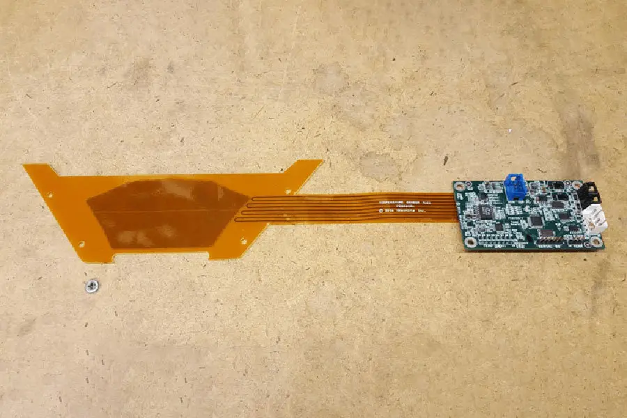
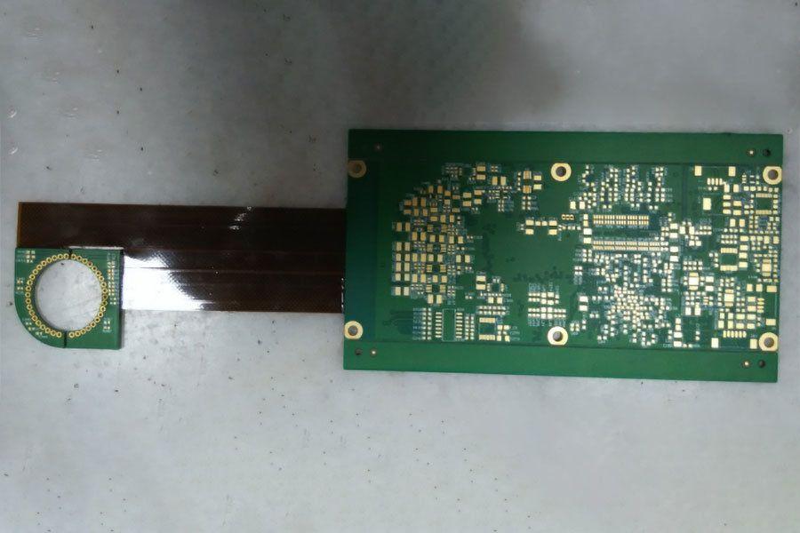
The application in question is a proprietary temperature measurement circuit made up of two parts: A four-wire probe and a traditional PCB.
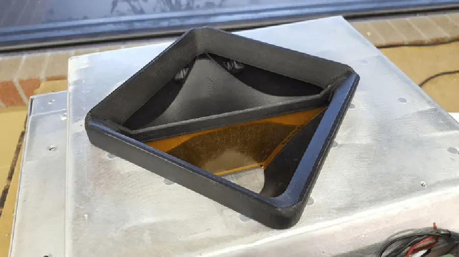
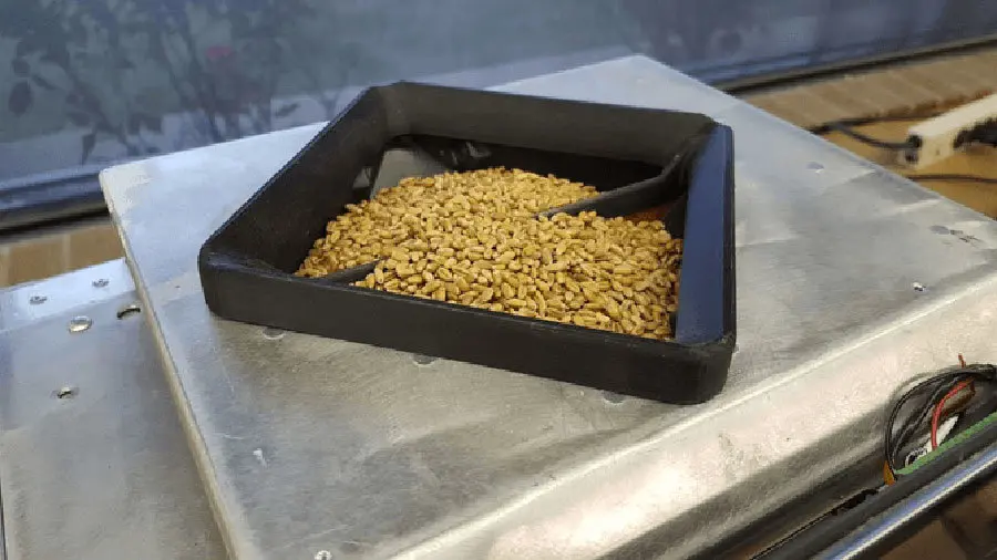
The probe is a very basic flex circuit, consisting of a set of long, thin copper traces and a stiffener that acts as a frame. The copper traces of the probe are soldered to the PCB to form the complete temperature measurement system. The probe sits in a funnel that receives grain samples. The stiffener provides a means by which to anchor the probe. The area containing the copper traces does not necessarily need to be flexible. It needs to thin or have a low thermal mass to allow for extremely rapid and accurate temperature measurement. As the images below suggest, this circuit will be continuously exposed to light abrasion in the form of corn, soy, wheat, and lima beans. The expected lifespan of an agricultural grain moisture meter is 20 years. One of the first problems that we need to solve is one of confidence that this light abrasion will not allow the “skin” of the flex circuit to wear in a way that would cause the copper traces to be exposed to the environment or the moisture in the grain samples. Abrasion aside, any long-term penetration of oxygen or other corroding elements would cause the copper trace to react differently and, therefore, the reading to drift. To summarize, the “skin” or other coatings atop these traces need to insulate the copper from corrosion, oxidation, moisture, and abrasion for 20 years. A tall order, eh?
We would also like to place three components (2xRTDs and a resistor) in the middle of the copper probe area. These components would need to be similarly shielded from the environment and moisture in the grain samples. I have imagined that a potting compound would achieve this end. This will come up again in the latter half of the email.
The second and third problems go hand in hand. First, this method requires us to manufacture and connect two boards. Second, it is relatively easy to tear the flexible leads that connect the two rigid bodies during the installation process. I would like to investigate combining the probe and PCB. The resulting board would be rigid except for a large area where the copper traces would be. This flexible portion would also harbor the aforementioned three components (2xRTDs and a resistor).
The fourth problem with our current application is a vulnerability to the abundant moist grain dust that will accrue on every unmolested surface of the device over the product’s lifespan of two decades. Ideally, the combined probe and PCB would be in some way dust-proof and vapor-proof. As noted above, I have imagined that this could be achieved with some sort of potting compound, but I am not a flex circuit fabricator.
Sterlite is not a high volume manufacturer. We estimate that we will sell 200 of this model per year post federal certification process. We are interested in design services that would perform the combination of the probe and PCB. We are also in the market for a party that could modify the current software that drives the temperature measurement system.
I have attached two board build packages to this email. The PES060R1 package is for the temperature probe. The PES058R3 package is the rigid-flexible PCB. I do not expect that you will use these packages to make any combination happen. In fact, I would ask that you do not at this time. I am far more interested in your thoughts on using flex technology to solve the above problems. These builds are attached for your reference in providing said feedback. If you are confident that a more robust application of flex technology could solve these problems, I would like to continue the conversation with more specifics. Thank you for your time and consideration.


