What Are Rigid-Flex PCBs
The development of computer technology and electronics into practically every part of our lives makes it easy to overlook or disregard the foundation upon which they are built: printed circuit boards, also known as PCBs.
Did you know the first-ever printed circuit board (still used today) was designed and developed in the 1930s by Austrian inventor Paul Eisler? Eisler designed PCB to operate a radio system in 1936 to build on a circuit design previously patented by Charles Ducas in 1925.
The technique was immediately adopted by the United States military operations, which utilized it in proximity fuses during World War II. Since its introduction to the public in 1948, PCB, also known as printed wiring boards (PWBs), have progressed in design and functionality.
Transformation of PCB's Over the Years
Compared to modern designs, the traditional PCBs are almost unrecognizable. Creating an electrical channel on an insulating substrate to facilitate the control and movement of electrical current was the essential premise of the design process. Several modifications and improvements have been made to the concept throughout the years to make it even better.
Modern electronics benefit from the advancement of materials and computerization, which has allowed PCB to evolve into Rigid-Flex hybrid and multilayered boards. The Rigid-Flex PCB is the most recent advancement in printed circuit board technology.
Flexible layers are incorporated into the rigid framework to balance the complexities and dependability of a hardboard circuit. Rigid-Flex Circuit Boards are smaller, thinner, and more flexible, allowing them to be used in irregularly shaped or particularly compact devices.
Today, PCBs are used in every industry. They have surpassed the stigma associated with chemical PCBs and are simply referred to as private circuit boards. This has occurred primarily due to the phase-out of chemical PCBs over the previous four decades. As printed circuit boards continue to develop, it can be assumed that they will become even smaller and more complex in the coming years.
Types of PCBs in Modern World
Manufacturing techniques, design parameters, and application requirements for printed circuit boards (PCBs) are grouped into different medical, automotive, defense, and space exploration industries.
More complicated designs based on consumers' demands and expectations pave the way to produce various printed circuit boards. Single-Sided, Double-Sided, Multilayer, Rigid, Flex, and Rigid-Flex PCBs are found in different industries today. Forget the rest, and let's focus on the most commonly used PCB—Rigid Flexible Circuit Board.
Understanding Rigid-Flex PCB
RFPCBs incorporates flexible technologies and rigid board in a single application. Depending on the application design, PCBs, which can be rigid or flexible, are typically composed of multiple layers attached to one or more rigid boards from outside and from within. During the manufacturing and installation process, the flexible substrates are typically molded into a curve to maintain a consistent state of flex.
Advantages of Rigid-Flex PCB
When Rigid-Flex pcb boards are used for interconnections, the necessity for connectors, which are large and inconvenient, is eliminated, resulting in significantly lighter RFPCBs.
Since Rigid-Flex PCB designs are made in three dimensions, they are a little harder to design due to the twisting and folding of the board to form any required shape for the product. However, Rigid-Flex material allows building the board compactly. Their lightweight nature makes them an excellent choice for various applications in aircraft, medical technology, and consumer electronics. Other advantages include:
• 360-degree bendability.
• Lightweight.
• Reduced space requirement through the 3D ability.
• Shock resistance.
• Fewer solder joints assure higher connection reliability.
• Simplified PCB assembly processes.
Rigid-Flex PCB Manufacturing Process
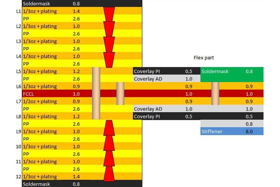
Since its inception, the production process for RFPCBs has evolved to become even more refined. In recent years, the development of a revolutionary Rigid-Flex PCB manufacturing technology has resulted in using FR4 (glass fiber epoxy resin) as a rigid external board, with a solder mask placed on top of the rigid layer to secure the circuit.
Furthermore, the flexible substrate is made of a double-layer polyimide (PI) board coated with copper for further strength. At last, an acrylic film is used to keep the flexible design pattern attached to the substrate. To develop Rigid-Flex circuits, the following steps are followed by PCB manufacturers:
• Preparation of the Base
• Constructing a Circuit
• Etching the Copper Foil
• Drilling with Precision
• Hole Plating
• Covering the Boar with a Plate
Demand for Rigid-Flex PCB Designers
Due to the miniaturization trend, there is a high demand for PCB designers proficient in Rigid-Flex design. Before you begin, it's crucial to understand that building a Rigid-Flex PCB takes a different set of abilities than developing a standard PCB.
A Rigid-Flex design should be typically installed in an enclosure, and the mechanical features of the design must be taken into consideration. However, because the flexible section of the PCB is sometimes bent to a certain degree, you'll need to consider the mechanical stress placed on the material. The bend line, also known as the bend area, must be handled to avoid early failure.
If possible, avoid using vias and pads at the bent areas because the mechanical stress may cause the paddings to break down. The routing of traces parallel to the bending line is also essential for maintaining structural stability. In addition to the current traces, you can add false traces to the bend area to make it stronger.
Rigid-Flex PCBs at HemeixinPCB
RFPCBs have been at the forefront of printed circuit board technology. At HemeixinPCB, we take pride in delivering the highest-quality printed circuit boards (PCBs) in the market. Each of our Rigid-Flex PCBs is subjected to extensive quality assurance testing to ensure that they meet industry standards. Our manufacturing facility is located in Shenzhen, China. To learn more about our cutting-edge technologies, please contact us or request a quote today.
HemeixinPCB
Wanxia Industrial Park, Tongfuyu Industrial Area,
Shajing Town, Bao'an District, Shenzhen, China
+86-755-2758-6529
This email address is being protected from spambots. You need JavaScript enabled to view it.


