Rigid-Flex PCB FAQ
What Is a Rigid-Flex PCB?
Rigid-flex PCB is a time-proven, well-understood technology initially used within the military/aerospace industry decades ago.
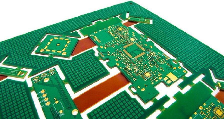
With a rigid-flex PCB, flexible circuit substrates and rigid circuit substrates are laminated together. Rigid-flex PCBs cross the boundaries of traditional rigid PCBs and the unique properties of flex circuits that use high-ductility electrodeposited or rolled annealed copper conductors photo-etched onto a flexible insulating film.
Flex circuits include stackups made from a flexible polyimide such as Kapton or Norton and copper laminated together through heat, acrylic adhesive, and pressure.
Flexible circuit boards by themselves may not stand up to the wear of certain challenging applications, but standard rigid boards tend to be heavy and take up a lot of space. Combining rigid boards with flexible circuits reduces weight and space, giving you a streamlined product you can use in a wide variety of industrial situations.
Rigid-Flex PCBs Materials
What are the differences of LCP compared to Polyimide?
The most commonly used rigid-flex PCBs materials are:
1. Substrate Materials – The basic material used for rigid-flex PCB manufacturing is woven fiberglass, which is thoroughly impregnated with epoxy resin. However, epoxy imprinted fiberglass is not always a reliable solution as it fails to resist frequent vibrations, shocks, and constant movement. Hence, for applications in demanding environments, rigid-flex circuit boards are manufactured using:
2. Polyimide – Polyimide is largely preferred over epoxy resins due to its versatility, toughness, and resistance to constant movements and vibrations. Also, the material shows impeccable heat resistance, making it ideal for applications in environments of elevated and fluctuating temperatures.
3. Polyester (PET) – Usually available in 25–125 microns thickness, this substrate material is chosen for its excellent flexibility and electrical properties. This material also exhibits outstanding chemical and moisture resistance. Hence, it can be used reliably in aggressive industrial environments. Selecting the right substrate material is crucial as it determines the strength and durability of the entire assembly. A substrate must be chosen after analyzing its dimensional stability, thermal resistance, electrical properties, flexibility, and chemical resistance, among others.
4. Conductor Material – Copper is the most commonly used and readily available conductor material for rigid-flex circuit board assembly. The material is preferred due to its benefits such as high workability and good electrical characteristics. For circuitry applications, two forms of copper foils are typically used – electro-deposited and rolled copper foil. Both these foil forms are available in various thicknesses and weights. They are subjected to surface treatment before they are used for the board assembly. Usually, a thin layer of zinc is applied to enhance the longevity of the foils. Also, the foils are chemically treated to reduce bond degradation, increase adhesion, augment bond strength, and protect from oxidation.
5. Adhesives – Adhesives play an important role in extending the service life of rigid-flex boards. They are responsible for making a secure connection between the substrate and conductor materials. Deciding on the type of adhesives and the required thickness to bond substrate and conductor is the most crucial part in rigid-flex circuit board manufacturing.
Amongst several adhesives available, the most common types used to manufacture rigid-flex boards are:
1. Polyimide Adhesives – This material is largely chosen due to its excellent temperature resistance, i.e. up to 500ºC. Due to their extreme heat resistance, polyimide adhesives are usually used in applications in defense, military, and power generation applications. Also, they are selected predominantly to produce multi-layer circuits due to their low coefficient of thermal expansion.
2. Polyester Adhesives – This is a relatively cheap adhesive used in the fabrication of simple rigid-flex PCBs. This material features low bond strength. Also, it cannot resist elevated or fluctuating temperatures. Due to these reasons, today’s rigid-flex manufacturers are opting for modified polyester adhesives. The advanced forms of polyester material possess excellent versatility and good heat resistance properties, making them reliable for use in the assembly of complex boards.
3. Acrylic Adhesives – This adhesive material has several superior features. Some of these include excellent thermal stability, outstanding chemical/corrosion resistance, and ease of application. Also, they are relatively cheap and readily available as compared to the other types of adhesives.
4. Epoxies – This is the most commonly used adhesive type for rigid-flex manufacturing. They can withstand elevated/fluctuated temperatures and can resist solvents and other chemicals. Also, they are extremely flexible and possess excellent bond stability. Today’s manufacturers improve the flexibility of epoxies by adding a small amount of polyesters.
5. Protective Coatings – The surface of rigid-flex PCBs are comprehensively coated using protective films. This helps PCBs resist chemicals, oils, hydrocarbon solutions, dust, and other contaminations. The protective coating is selected after understanding the types of materials used in the assembly, compatibility of PCB components with the coating material, and most importantly the application areas.
The most commonly used forms of coatings are:
1. Cover Lays – When a flexible film like polyester or polyimide is combined with a suitable adhesive, the resulting product is a cover lay. Cover lay has three major roles to play in a rigid-flex PCB assembly. First, to provide comprehensive protection to the entire assembly. Second, to access circuitry areas like circuit pads for further processing. Third, to augment the reliability and resilience of the circuitry.
2.Cover Coats – Unlike cover lay method, a thin coating of liquid acrylated epoxy and acrylated polyurethane is applied onto the circuitry surface. The liquid coating is applied using several methods, one of such is screen printing. The coating is then thermally cured.
Besides these materials, there are several other optional materials used in the fabrication of rigid-flex PCBs to augment their operational excellence and reliability. These include anti-tarnishing coatings, and backing substrates. PCB manufacturers choose these materials as per the needs of customers, and specific application requirements.
The material used greatly determines the quality and overall functioning of the rigid-flex boards. As mentioned earlier, board materials must be carefully chosen after analyzing several criteria including cost, shelf life, and electrical requirements of the circuit, among others. This helps produce rigid-flex circuit boards that provide many years of reliable and trouble free service.
Additional Considerations
Designs that have one or more of the following may require the use of coverlay throughout in specific areas or layers:
ZIF finger area Polyimide stiffener(s)
FR4 component area rigidizing stiffener(s)
Silver Ink Shield Layer(s)
EMI & RF Shielding film(s)
Pressure Sensitive Adhesives (PSA)
The materials above may not sufficiently adhere to LPI and pass IPC quality control requirements.
Can you comment on the stack-up use of RA copper/ED copper in static/dynamic installation?
Please note:
1.RA copper has a preferred direction “MD” = “machine direction”. In the other direction the bending capability is remarkably worse
2.In case of flex-rigid with flex layer outside generally also the flexible area is plated – so this copper quality is ED-copper
3.More copper qualities are specified in IPC-4562 standard
Spacings and Creepage - Can we treat the flex section (Polyimide) as standard FR4?
But Polyimide, i.e. DuPont Pyralux AP or Panasonic R-F77x only has CTI level 4.
On the other hand almost all designs do not have free copper on the flex layer without a barrier in between like soldermask or coverlay. In addition, in case of flex inside the stackup all copper is completely covered by rigid material in the rigid sections or coverlay in the flexible sections.
Regarding isolation, is Polyimide in the same material group as FR4? (IIIa/b)?
What is the minimum annular ring for vias in flex-rigid technology?
For example: according IPC class 2 up to 90° breakout of hole from land is allowed, for IPC class 3 the annular ring has to be minimum 50µm for external layers and 25µm for internal layers. The use of teardrops basically improves the manufacturability
Is it possible to get stack-up drawings from you?
Flex inside or outside – what are the advantages/disadvantages and your recommendation?
A.1 Flex layer ⇒ outside as 1F-xRi ⇒ favourable
B.2 or more flexible layers ⇒ inside than xRi-yF-xRi ⇒ more expensive
C.dynamic application with many bending cycles ⇒ inside + RA copper
In individual cases, e.g. with sensitive and very fast signals over the flex range, an asymmetrical design can offer 2F-xRi signal technical advantages. However, the production of such a setup is more complicated than a symmetrical setup xRi-yF-xRi. With regard to the permitted minimum bending radius, the 2F-xRi setup offers no advantage over an xRi-2F-xRi, but at the same time there is a risk of bowing and twisting due to the asymmetry in the stack-up.
What is the maximum copper thickness with flex-rigid?
Note: For plated outer layers IPC-6013C Table 3-19 applies.


