Basics of Flex Circuit Board Design
The development of computer technology and electronics into practically every part of our lives makes it easy to overlook or reject the foundation upon which they are built: printed circuit boards, often known as PCBs.
Even though electronics and their components are widely spread in our everyday lives, they have only been around for a century. The original printed circuit boards (PCBs), still used today in electronic devices, were created and developed in the 1930s.
Although all printed circuit boards (PCBs) perform fundamentally the same duties, there are three primary types: rigid, rigid-flex, and flex. Each of these types differs in design and construction, but they all serve the same purpose.
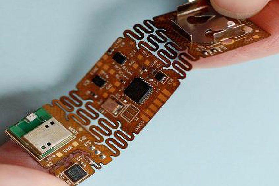
Considering their names, rigid printed circuit boards (PCBs) cannot bend, but flexible printed circuit boards (PCBs) can be bent and tailored to suit specific products or systems. Finally, a rigid-flex board is a hybrid of rigid and flexible circuit boards.
To fully understand the growth of the flexible printed circuit board, it is necessary to examine the history of electricity in depth. What's notable about this is that, before the digitization of the printed circuit board, most materials for wires and circuits boards were highly flexible.
History of Flex Circuit (PCB) Design
In the long history of the electronic/electrical industry, flexible PCBs have been one of the most prominent electronic components.
A patent for flexible printed circuit board technology was granted in the early years of the 21 century when the researcher attempted to simplify the early telephone exchanger's circuit layout by embedding electrical wires between two separated materials.
As early as the 20th, several scientists began focusing their attention on electrical connectivity methods, as shown by Thomas Edison's experimental record, the pioneer and forerunner of flexible PCB.
Frank Spange, Edison's assistant, questioned how to construct the flexible PCB circuit track onto the isolated material. Edison suggested incorporating carbon power into epoxy glue and smearing it over linen fabric paper. Yet, there is no proof to back up his ideas and put them into practice. However, this approach is comparable to the commonly used polyamide flexible PCB construction.
Flexible PCBs were utilized in electrical and electronic products until the end of the Second World War. German scientists used flat circuit track technology to the tank tower and V2 rocket at this stage. Additionally, Pat Bryan, the pioneer of flexible PCB in the United States, said that in the early 1950s, US space researchers conducted research on a V2 rocket and discovered flexible PCB, which led to its widespread use in the United States.
Bryan returned some flexible PCBs to the California center while working in the LOCKHEED, and they were eventually employed in the aerospace and other industries. Today, PCBs are used interchangeably in every sector. As flex circuit boards continue to develop, it can be assumed that they will become even smaller, more complex, and flexible in the future.
Basics of Flexible Circuit (PCB) Design
In today's world, a flexible circuitry is a fantastic option for various electrical applications. Although compact and lightweight, it can be very robust if appropriately constructed.
Since it bends, a flex circuit has unique requirements that differ from ordinary rigid circuits. It is necessary to consider the materials used, the circuit architecture, where features are placed, and the number of layers in the circuit throughout the design process of the circuit.
Special attention should be given to the degree to which the circuit will be bent, the tightness, and how frequently the circuit will be flexed. To effectively use the benefits of flex circuits, the designer must understand the unique needs of this technology and operate within those requirements.
Here are a few things to keep in mind when designing flexible circuit PCB.
The most effective method of centering the neutral bend axis is to use balanced construction. Get the neutral bend axis near the center of the stack to maintain both of these distances and destructive forces that emerge from them. As close as you place the neutral bend axis to the center of a circuit's material stack during flexing, the more evenly it will spread over its remaining layers.
The less a circuit is flexed, the lower the possibility of damage. The greatest angle through which a circuit should be bent without breaking is 90°. It is possible to bend a correctly designed circuit more than 90 degrees once during installation. For dynamic applications, such as those where the circuit will be bent, flattened, and then bent several times again, the bend should not be more than 90°.
When flexed, the possibility of damage is minimized due to the reduced thickness. To reduce the circuit thickness in the bend area, it is necessary to reduce the base copper weight and dielectric thickness. Designers may also lower the thickness of their designs by using adhesive base materials.
A larger radius combined with a tighter bend reduces the chances of circuit damage. The same right-angle may typically be obtained with either a sharp (small radius) or a more progressive (large radius) angle when making a 90-degree bend. The latter is more secure in terms of the flex circuit. (Please keep in mind that the bend radius is measured from the inner surface of the bend).
Careful design and consideration of these factors should result in a suitable circuit for its intended use and provide all of the advantages of flex circuitry at the lowest possible cost. When in doubt about the best way to accomplish specific objectives in a flex circuit application, joining hands with an experienced manufacturer may be your best bet.
Best Flexible Circuit Design Manufacturer – HemeixinPCB.com
HemeixinPCB.com has seen consistent growth throughout its existence due to providing a highly valued combination of technological expertise and cost-effective manufacturing.
Located in Shenzhen, China, HemeixinPCB is a prominent supplier of time-to-market manufacturing services to the printed circuit board sector.
From quick-turn prototypes through ramp-to-volume production to full-scale production, every element of the manufacturing process is overseen and handled by highly skilled professionals.
Please view our complete PCB prototype assembly-delivery services here. For more information, contact us today!
HemeixinPCB.com
Wanxia Industrial Park, Tongfuyu Industrial Area,
Shajing Town, Bao'an District, Shenzhen, China
+86-755-2758-6529
This email address is being protected from spambots. You need JavaScript enabled to view it.


