How to Calculate the Flex PCB Bend Radius
Circuit boards have allowed humanity to step into the modern era. One can argue that they are the cornerstone of humanity's most recent achievements. All scientific research, whether concerning the life sciences or modern physics, requires complex electrical devices for accurate analyses.
Consequently, circuit boards provide the means to use electricity and breathe life into appliances and devices. Technology would merely cease to exist without them since they are virtually the foundation upon which all electrical products are built.
In recent times, they too have undergone quite some change. We now have printed circuit boards that aid us in developing increasingly intricate applications and systems. Printed circuit boards are divided into rigid boards, flex circuit boards, and rigid-flex circuit boards.
Perhaps, flex circuit boards can arguably be considered the most innovative of the three. In this article, we will explore their benefits, understand flex PCB bend radius, and finally teach you how to calculate flex PCB bend radius.
Flex Circuit Boards
As the name suggests, this particular category concerns printed flexible circuit boards. These can be bent, flexed, or manipulated to fit inside an electrical design. The flexibility affords them greater versatility than traditional rigid circuit boards. Therefore, flex circuit boards are vital components in designs that require utilizing limited space.
As a result, their use has become increasingly popular in modern consumer electronics, smartwatches, information, and medical appliances. When correctly designed, they can be subjected to thousands of looping or bending cycles. It affords them uniqueness as well as a set of advantages over their rigid counterparts.
Flexibility
It goes without saying that flexibility is one of the biggest advantages of using flex circuit boards. This ability allows for more creative freedom and the ability to fit the circuitry into the design, limiting any creative compromises.
Reduced Weight
The circuit boards have to be very light and thin to achieve flexibility. This results in an overall reduction in weight which is an important factor in the modern world where lightweight products are preferred over heavier ones. The lightweight design of flex circuit boards also allows for increased flexibility and better shock absorption, which increases the long-term reliability of products.
Connectivity
Flex PCBs also increase the range of connectivity in a device and its electrical components. Their use in dynamic flex circuit applications is particularly popular since they require circuit boards that can be bent or flexed for an indefinite number of cycles. This makes them the top choice for use in foldable electronics.
Flex PCB Bend Radius
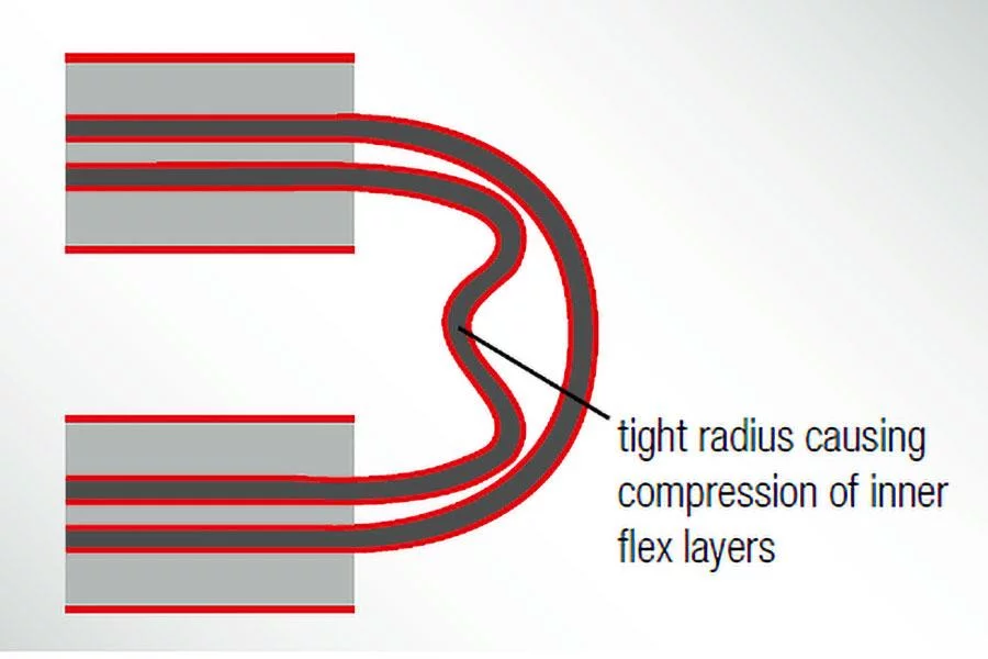
There is, however, a limit to the amount of strain flex PCBs can be subjected to. When they are bent out of shape, the internal bend experiences compressive forces while the external bend experiences tensile forces. Knowing the limits of these forces that the circuit board can withstand helps with the continued functionality and enhanced performance of an electrical device.
The bend radius is a measure of how much you can bend a flex circuit board without causing any damage or shortening its lifespan. The smaller the bending radius of a circuit is, the more flexible it will be. There are three types of design standards for flex circuit boards:
1. Flex to Install
This is also called the stable flex and involves the flex layer to be bent into shape to fit into a design. The bend is introduced in the beginning, and the layer is not subjected to further stress. For one or two layers, the minimum bend radius can be 6X, while for multiple layers, it can be up to 12X.
2. Dynamic Flex
This design involves repetitive bending of the design; therefore, limiting it to two layers is recommended. The copper should be allowed to sit on the neutral axis, which is the point that experiences minimal strain or stress. The minimum bending radius is roughly around 100X.
3. One Time Crease
Minimum bend radius is irrelevant in this design since the flex layer is creased before being installed into the design. Very thin layers and copper weights are recommended. The copper should be placed as near the neutral axis as possible.
How to Calculate Flex PCB Bend Radius
The minimum bending radius is calculated as a multiple of the final circuit board thickness and the ratio of the desired application (stable or dynamic) and bend radius (r):
Ratio = r/h; where r = bending radius, and;
h = overall height of the flexible part.
These are the bending radii for different layers of stable and dynamic flex boards according to IPC-2223:
|
|
Stable |
Dynamic |
|
Single Layer |
10:1 |
100:1 |
|
Double Layer |
10:1 |
150:1 |
|
Multi-Layer |
20:1 |
Not recommended |
To calculate the minimum bending radius of a single-layered dynamic flex circuit board with an assumed thickness of 90 µm, we will confirm the bending radius ratio from the table above and multiply it with the thickness of our application:
Min. bending radius = (r/h of single layer dynamic flex) x application thickness
= (100:1) x 90 µm (or 9 x 10⁻⁶)
= 9 x 10-4 = 0.9 mm
Therefore, the flex circuit board will have a resulting minimum bending radius of 0.9 millimeters. Similarly, you can calculate flex PCB bend radius for any application as long as you consult and tally accurate values from the abovementioned table. For more information on design guides for flex circuit boards, understanding the flex PCB bend radius, or for more innovative circuitry, visit Hemeixin Electronics.
They are one of the leading manufacturers of flex circuit boards, among other modern design models. They offer the best circuit boards to customers at affordable rates because you deserve the best solutions for your electrical designs! Take and look at their products and get a quote today!