Rigid-Flex PCB Bend Radius
Electricity is the source of humankind's technological success. We have advanced a great deal from the times of steam engines and the wheel to the current world order. Humans have found innovative ways to use electrical energy in their inventions.
These feats have allowed human beings to accomplish feats that would have been considered impossible in the past. Many of these advances can be owed to the use of circuit boards that allow us to harness electrical energy and power appliances. From tiny smartphones to large supercomputers, all electrical appliances require the use of circuit boards.
Similarly, circuit boards, too, have undergone drastic evolutionary processes. Our current technology line offers printed circuit boards(PCBs) that are far superior to their standard counterparts.
Printed circuit boards are a means to connect electrical components to form a fully functional device. They fall into three distinct categories depending on their design:
1. Flex Circuit Boards
2. Rigid Circuit Boards
3. Rigid-Flex Circuit Boards
In this article, we will learn what rigid-flex circuit boards are, and something called the rigid-flex PCB bend radius.
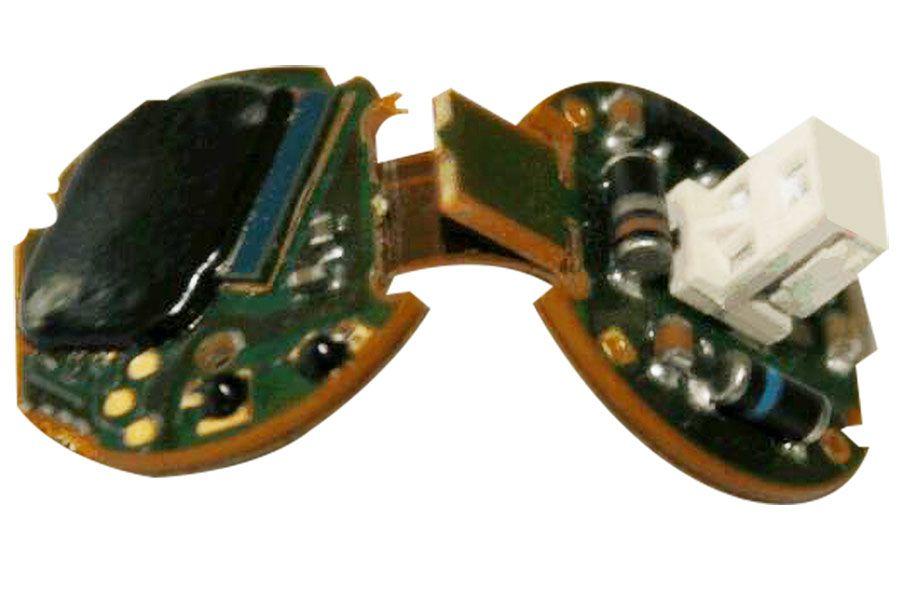
Rigid-Flex PCB Boards
Considered one of the latest advancements in the circuitry sector, rigid-flex PCBs incorporate the benefits of rigid and flex circuit boards while avoiding their limitations. The resulting hybridized model is superior in design and function to both its parents.
Rigid-flex PCBs combine the rigidity of rigid boards and the flexibility of flex boards into a single functioning unit. The flexible substrate is molded into a constantly flexed design and contained within a rigid board. The design allows for the printed circuit board to be used in devices with limited space.
The rigidity to flexibility ratio allows them to fit into the device design while successively removing the limitations brought on by flexible cables and connectors. Removing the connector cables provides increased performance and long-term device reliability; this is because the cables connecting the electrical components are prone to wear and tear, which can lead to the device losing functionality.
Let's look at some of the advantages of using rigid-flex PCB.
One Rigid-Flex Board vs. Five Rigid Boards
Sometimes, a device will require flex cables to connect up to five rigid boards to meet the design demands. In such instances, a better and cost-effective choice is to use a rigid-flex circuit board that has both flex qualities and rigidity.
The design is based on 360° bendability that limits the use of soldered joints or connections and results in increased space saving and simplicity in the PCB assembly process.
High-Density Applications
Modern devices require dense networks of circuitry, which can be difficult to accomplish using discreet wiring. Rigid-flex circuit boards offer multiple copper layers to offer high-density circuity for such applications.
High Reliability and Durability
Rigid-flex PCBs are able to withstand more shock and vibrations than flex PCBs due to the absence of connectors. This allows them to increase reliability and durability in applications that require moving parts or the printed circuit board to flex for an indeterminate number of cycles.
Rigid-Flex PCB Bend Radius
There is a limit to how much a printed circuit board can be bent. Any stress exerted beyond this threshold can result in copper stretching or breakage, causing the device to lose function.
Rigid-flex PCB bend radius is a measure of how much strain can be exerted upon the circuit boards without causing them to fail or break. The deformation of copper is used to determine the bend radius, which is calculated as a multiple of the finished flex thickness.
There are three categories defined in the design standard for flex print boards, and we use them for rigid-flex circuit boards as well because it’s the flex layer that generates bending capability. Let’s learn about the categories and rigid-flex PCB bend radius.
Dynamic Flex
In this design, the flex layer will be subjected to repetitive bending as part of its function, so the design should be limited to one or two layers to ensure maximum bendability. The copper is allowed to rest on the neutral axis of the bend radius to prevent deformation. The minimum bend radius is approximately 100x times the finished flex thickness of the printed circuit board.
Flex to Install
The design involves the flex layer to be bent into shape and fit into the design without subjecting it to further strain. The layers can be greater than two, but it is preferred to only incorporate one or two layers. The minimum bend radius will be 6 times the layer thickness for 1 to 2 layers, and it will be 12 times for 3 or more layers.
One Time Crease
This design results in a zero bend radius by inducing a crease or a fold in the printed circuit board before installing it into the appliance. Therefore, the bend radius does not play a significant role in this design, but it is recommended to use very thin layers and copper weights. The copper is also allowed to rest on the neutral axis, while the recommended number of layers is 1.
The effectiveness of rigid-flex PCB is reliant on their rigidity to flexibility ratio. It is very important to meet the printed circuit board bend requirements for a particular design, which is why sourcing these boards is crucial for any appliance manufacturer.
We recommend Hemeixin Electronics for all your PCB needs since they are one of the leading manufacturers of printed circuit boards and offer the best custom-built models for all your application needs.
From choosing the best materials to even offering customers specific design guides, Hemeixin Electronics is bringing more innovation to printed circuit board technology. Do visit their website to see for yourself, and also to get instant quotes!


