Rogers 4350B vs Megtron 6 vs Tachyon100G - High speed pcb Laminates Comparison Chart
PCBs are evolving with the continually increasing demands of the electronics and telecom market. We are sitting on the eve of widespread deployment of 5G wireless technology across the globe. This will mean that the underlying electronic devices (primarily cell phones and other network-dependent electronics) will need to cope with the high-frequency
demands of the 5G technology.
When it comes to high frequency PCB circuits, the most commonly used PCB material, FR-4, doesn't seem to cut it. FR-4, while being widely used, tends to be a very loss-generating material in high-frequency circuits. For such circuits, specialized materials (laminates) are chosen. There is a wide variety of them available in the market, from season manufacturers like Isola, Itera, Taconic, Rogers, and Panasonic.
Among them, two of the most commonly used materials are Rogers Ro4350B and Panasonic Megtron 6. Let’s see the difference between the two.
High speed pcb Material Properties and Insertion Losses
| Rogers Corporation Rogers 4350 | Panasonic MEGTRON 6 | Isola Group I-Speed | Isola Group FR408HRIS | Isola Group Standard FR4_LP | Isola Group Standard FR4_LP | |
|---|---|---|---|---|---|---|
| DK | 3.48 | 3.49 | 3.25 | 3.65 | 4.4 | 4.4 |
| DF | 0.0057 | 0.006 | 0.0074 | 0.0115 | 0.017 | 0.017 |
| Surface Roughness (µm) | 0.5 | 2 | 2 | 2 | 5 | 8 |
| Copper Conductivity (S/m) | 4x10⁷ | 4x10⁷ | 4x10⁷ | 4x10⁷ | 4x10⁷ | 4x10⁷ |
| Cost | 3.8X | 3.5X | 2.3X | 1.7X | 1.2X | 1X |
| IL @ 2.4 GHz (dB/in) | Rogers Corporation Rogers_4350 | Panasonic MEGTRON 6 | Isola Group(I-Speed | Isola Group FR408HRIS | Isola Group Standard FR4_LP | Isola Group Standard FR4_LP |
|---|---|---|---|---|---|---|
| W = 4 mil | –0.318 | –0.469 | –0.474 | –0.528 | –0.658 | –0.692 |
| W = 6 mil | –0.246 | –0.362 | –0.367 | –0.422 | –0.539 | –0.565 |
| W = 8 mil | –0.211 | –0.302 | –0.308 | –0.359 | –0.467 | –0.488 |
| W = 10 mil | –0.184 | –0.263 | –0.272 | –0.323 | –0.427 | –0.444 |
| W = 12 mil | –0.167 | –0.233 | –0.246 | –0.293 | –0.399 | –0.414 |
| IL @ 4.0 GHz (dB/in) | Rogers Corporation Rogers_4350 | Panasonic MEGTRON 6 | Isola Group I-Speed | Isola Group FR408HRIS | Isola Group Standard FR4_LP | Isola Group Standard FR4_LP |
|---|---|---|---|---|---|---|
| W = 4 mil | –0.452 | –0.667 | –0.679 | –0.765 | –0.954 | –1.002 |
| W = 6 mil | –0.354 | –0.518 | –0.529 | –0.616 | –0.794 | –0.829 |
| W = 8 mil | –0.306 | –0.435 | –0.446 | –0.531 | –0.696 | –0.724 |
| W = 10 mil | –0.270 | –0.381 | –0.397 | –0.481 | –0.641 | –0.665 |
| W = 12 mil | –0.246 | –0.340 | –0.362 | –0.440 | –0.603 | –0.624 |
| IL @ 5.0 GHz (dB/in) | Rogers Corporation Rogers_4350 | Panasonic MEGTRON 6 | Isola Group I-Speed | Isola Group FR408HRIS | Isola Group Standard FR4_LP | Isola Group Standard FR4_LP |
|---|---|---|---|---|---|---|
| W = 4 mil | –0.531 | –0.774 | –0.788 | –0.896 | –1.126 | –1.178 |
| W = 6 mil | –0.417 | –0.604 | –0.618 | –0.728 | –0.942 | –0.981 |
| W = 8 mil | –0.362 | –0.509 | –0.525 | –0.628 | –0.831 | –0.861 |
| W = 10 mil | –0.321 | –0.447 | –0.467 | –0.572 | –0.768 | –0.794 |
| W = 12 mil | –0.294 | –0.400 | –0.427 | –0.524 | –0.724 | –0.747 |
| IL @ 6.0 GHz (dB/in) | Rogers Corporation Rogers_4350 | Panasonic MEGTRON 6 | Isola Group I-Speed | Isola Group FR408HRIS | Isola Group Standard FR4_LP | Isola Group Standard FR4_LP |
|---|---|---|---|---|---|---|
| W = 4 mil | –0.607 | –0.872 | –0.890 | –1.018 | –1.290 | –1.356 |
| W = 6 mil | –0.479 | –0.683 | –0.699 | –0.832 | –1.085 | –1.134 |
| W = 8 mil | –0.417 | –0.577 | –0.596 | –0.720 | –0.961 | –0.999 |
| W = 10 mil | –0.370 | –0.508 | –0.532 | –0.658 | –0.891 | –0.924 |
| W = 12 mil | –0.339 | –0.455 | –0.487 | –0.604 | –0.842 | –0.871 |
| IL @ 12.9 GHz (dB/in) | Rogers Corporation Rogers_4350 | Panasonic MEGTRON 6 | Isola Group I-Speed | Isola Group FR408HRIS | Isola Group Standard FR4_LP | Isola Group Standard FR4_LP |
|---|---|---|---|---|---|---|
| W = 4 mil | –1.099 | –1.440 | –1.485 | –1.754 | –2.307 | –2.694 |
| W = 6 mil | –0.882 | –1.147 | –1.191 | –1.466 | –1.996 | –2.275 |
| W = 8 mil | –0.775 | –0.983 | –1.032 | –1.294 | –1.792 | –2.020 |
| W = 10 mil | –0.695 | –0.878 | –0.932 | –1.198 | –1.683 | –1.877 |
| W = 12 mil | –0.642 | –0.795 | –0.863 | –1.115 | –1.607 | –1.776 |
Similarities between Rogers 4350B and Panasonic Megtron 6
Finding the low-loss material that will provide the best balance of performance and board cost for a given application is morecomplicated than simply comparing laminate datasheets and prices. Datasheets do not reveal which materials involve relativelymore or unusual processing steps during PCB fabrication, which can raise manufacturing cost. Consider Rogers 4350B andPanasonic Megtron 6, which have similar low Df and Dk values, have been used extensively in RF PCB applications, and areincreasingly being used for high-speed digital products.Both are based on hydrocarbon resins; the Rogers resin has a ceramicfi ller. Neither laminate is available clad with quarter-ounce copper. The thinnest foil available for the Rogers material is half-ounce,and for Megtron 6, one-third-ounce.Both materials are available with low-profi le foils to prevent signal refl ections at highfrequencies.
Both Rogers 4350B and Megtron 6 are specifically designed high-speed laminates. Both fall into the extremely low-loss category of laminates (if considered based on the loss). In terms of highest efficiency and least incurring losses, Rogers 4350B and Megtron 6 are second only to specifically designed extremely low loss, microwave laminates like Taconic RF-35TC.
Both the materials are very similar when it comes to many electrical and transmission characteristics. Take the signal loss, for example. Megtron 6 tends to be the superior material for frequencies below 5, but over that, Rogers 4350B has a slight edge (just a shade better than Megtron 6).
If we dive a bit deeper into the laminate material’s electrical performance properties, two other terms that you might have heard are Permittivity (Dk) and Loss tangent (Df). Megtron 6 has a Dk of 3.7 and Df of 0.002 at 2 GHz (3.3 and 0.004 at 10 GHz). Whereas Rogers 4350 has a Dk of 3.43 and Df of 0.0037 at 10 GHz. So in higher frequencies, Rogers 4350B has a bit of an edge in these commonly compared electrical characteristics.
But as you might have gathered by now, the differences between the two aren't very substantial in electrical characteristics and losses. So, where does the difference really come? Even if we take a transmission variable, peak-to-peak jitter value at 10 Gbps, there is only a minute difference between the performances of the two different laminates. Rogers 4350B noted 14.9 Ps, and Megtron 6 gave a value of 14.2 Ps.
Both materials are extensively being deployed in low-frequency applications. One such example was the use of Megtron 6 in IBM’s mainframes (z14) in 2017.
If we consider the construction of the two materials, Rogers 4350B is made from a glass-fiber reinforced hydrocarbon/ceramic laminate. The Megtron 6 comes in both PPO and PPE epoxy blend resins. They don't offer quarter-ounce copper-clad options.
Differences between Rogers 4350B and Panasonic Megtron 6
Some of the significant differences between the two laminates have to do with fabrication and options.
When it comes to foil thickness, Megtron 6’s thinnest foil of 1/3rd of an ounce is thinner than Rogers 3450B’s ½ ounce foil. Both are almost equally good at preventing signal reflections at high frequencies. Megtron 6 offers a wider variety of laminate choices, eight in total.
Also, compared to Rogers 4350B’s three prepreg choices, the thinnest of which is 3.6 mils, Megtron 6 offers 18 different thicknesses and a much wider variety (and thicknesses) of prepregs. This gives a lot more options when you are working with Megtron 6, especially as the layer count increases.
But even these are not the upshots of the differences between the two. The upshot is that ease and limitations of fabrications.
If you are working with Rogers 4350B, it's specific (and minimal) range of prepregs require special lamination cycle requirements. The prepregs require a higher-than-normal pressure to ensure proper lamination of the Rogers 4350B material. This adds to the fabrication cost. But it also has another impact. Rogers 4350B advises against etch-backs as well as using more than one prepreg layer. This usually limits the use of Rogers 4350B to a cap construction.
It might also have something to do with the low Tg of Rogers 4350B because it cannot go through multiple lamination cycles without adverse effects.
This limits the use and application of Rogers 4350B for a lot of different industry applications. Due to just allowing for cap construction, a board with this laminate cannot fully realize the power of high-layer counts PCBs and dense packaging.
This is where Megtron 6 is clearly the winner. The best part about it that there isn't any difference in the lamination of a Megtron 6 and the conventional FR-4. That means that every fabricator who has an assembly line poised for the traditional construction of PCB can easily work with Megtron 6. They don’t have to change pressure parameters, tweak temperature during assembly, and prepare for different cure times. This also means that Megtron 6 isn’t limited to cap construction. It can easily be designed in a foil construction as well.
To sum it up, Megtron 6 is relatively very easy to work with compared to Rogers 4350B. But the latter has a clear advantage in high-frequency circuits and is widely used in places where signal integrity and low losses are of paramount importance. But where ease of fabrication and design complexity are major considerations, Megtron 6 takes the cake.
Another major difference between the two is the basic cost. Rogers 4350B is easily three times the cost of Megtron 6. This becomes especially apparent in large scale fabrication. Because Rogers 4350B is expensive as material, as well as complex to fabricate, the large scale yield of Rogers 4350B based circuits sometimes becomes unfeasible.
Ultra-low transmission loss Highly heat resistant Multi-layer circuit board materials MEGTRON7 | R-5785(N), R-5785(GN), R-5785(GE), R-5785(R)
Due to our industry leading low dielectric constant and dissipation factor, these materials are suitable for high-speed data transmission by servers and routers using high - layercount, large-size PCB designs
Introducing MEGTRON 7, a multi-layer circuit board material with the industry’s lowest transmission loss, which meets the requirements for high-capacity and high-speed transmission of high-end networking equipment, thereby contributing to the improvement of their signal processing performance.
Ultra Low Transmission Loss: Dk = 3.6 @ 1GHz, Df = 0.0015 @ 1GHz
High heat resistance and reliability
Compatible with lead-free soldering
High speed PCB material Selection Guideline
For proper stackup selection for high speed signals in your PCB layout, follow these guidelines:
- Select a dielectric material with the lowest loss tangent and smaller dielectric constant, for example, the Megtron6 (df<0.002, epsr=3.1) is an appropriate choice.
- When they become available after vendor characterization, dielectric materials such as Megtron 6N/6G or Tachyan 100G are good selections.
- 25+G designs require special attention to material details including Fiberglass, Dielectric Matrix and Copper. The signal at higher data rate has higher frequency element and the wavelength goes on reducing. The change of fiber glass pattern, dielectric matrix pattern and copper pattern should be considered carefully. As for higher data rate (shorter signal wavelength), it appears to create more discontinuities and reflection with slight change. Please refer to PCB Dielectric Material Selection and Fiber Weave Effect on High-Speed Channel Routing for more information.
- Select smaller dielectric height for high speed signal routing.
- It requires smaller trace width for trace impedance target. There is always a trade off between selecting wider trace width and shorter trace width. The wider width has less skin depth and lower insertion loss but takes more space for routing.
- It also results in a smaller PCB height as well as smaller transition via height for achieving minimum impedance mismatching.
- Select enough stripline layers for all critical high speed signal routing.
- Hemeixin recommends stripline routing for all critical high speed signals (above 15 Gbps).
- You can route all non-critical high speed signals (below 15 Gbps) on a microstrip layer.
- Stripline routing has maximum isolation with other layers as long as both sides are reference planes. Hemeixin does not recommend dual stripline routing unless the signal routing on both stripline layers are perpendicular. This means, longitudinal broadside coupling of differential pairs should be avoided.
- Hemeixin recommends Stripline preferred over microstrip. If microstrip routing is selected, Hemeixin recommends removing the solder mask.
- Stripline routing requires smaller trace width, which results in more space for signal routing.
- Selection of a ground/signal/ground stackup combination for critical high speed signals.
- Selection of a ground/signal/ground combination may be feasible as long as the signal routing crossings on both stripline layers are perpendicular to minimize broadside coupling which results in cross-talk.
- Select enough power/GND layers to cover the power supply rails.
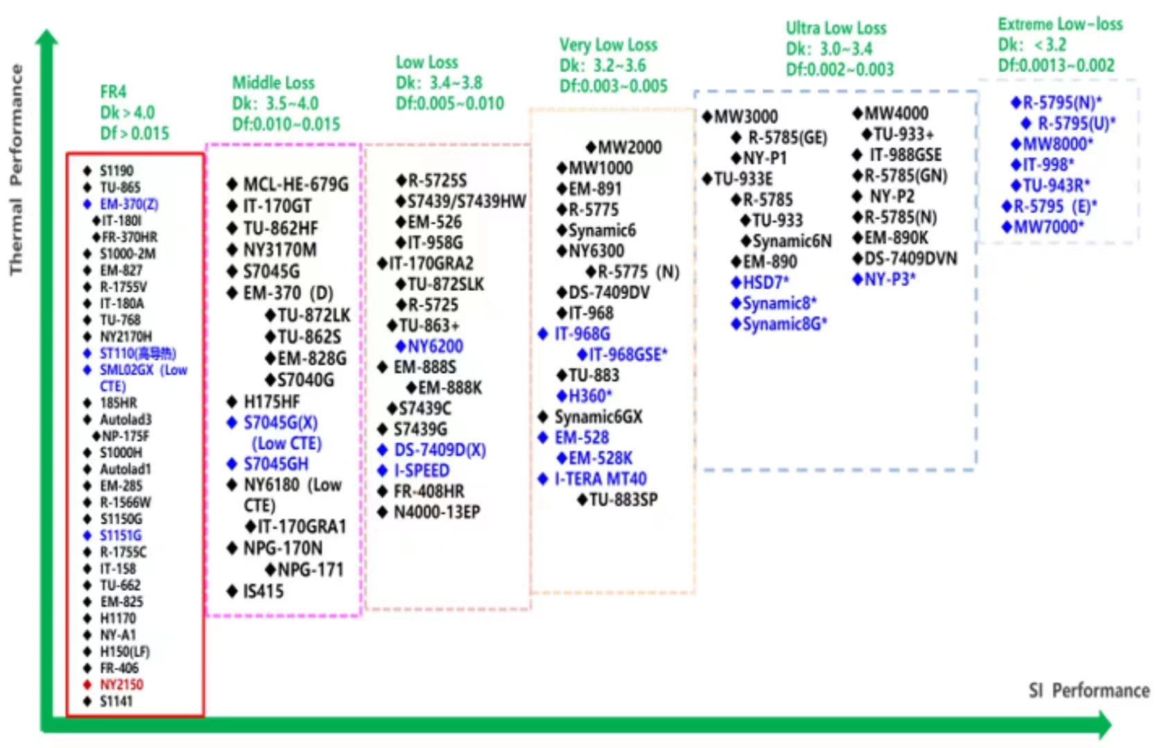
Below is a comparison chart sorted by Dielectric Constant and Dissipation Factor values. This chart provides the basic properties of the various laminates available
|
Material |
Relative Permittivity (Real Part) |
Loss Tangent |
|
Typical FR4 |
4 |
0.02 |
|
GETEK |
3.9 |
0.01 |
|
Isola 370HR |
4.17 |
0.016 |
|
Isola FR406 |
4.29 |
0.014 |
|
Isola FR408 |
3.7 |
0.011 |
|
Panasonic Megtron 6 |
3.4 |
0.002 |
|
Nelco 4000-6 |
4.12 |
0.012 |
|
Nelco 4000-13 EP |
3.7 |
0.009 |
|
Nelco 4000-13 EP SI |
3.2 |
0.008 |
|
Rogers 4350B |
3.48 |
0.0037 |

Copper thickness has not been encounter into the above approximate PCB attenuation equation. The thicker copper width, the less trace resistance.
Hemeixin recommends that the designers must consider an average of +/-5% variation into the loss obtained in figure PCB Trace Attenuation Comparison per 1” trace length for various dielectric materials, while trace width is 5 mil, results up to 20GHz due to some material tolerances by Fabrication Company.
An average surface roughness (approximately 2 µm) has been included into the approximate PCB attenuation equation for trace loss attenuation. For accurate loss calculation, Hemeixin recommends the designers to have at least 2.5D CAD analysis on transmission loss attenuation considering actual surface roughness, copper thickness and frequency dependent dielectric materials.
| Material | MEG4 | MEG6 | Tachyon100G |
| Average Loss per inch @14 GHz | 1.2 dB | 0.85 dB | 0.8 dB |
Overall, MEG6 and Tachyon100G materials are the best options for 28 Gbps high speed signals routing.
For more information on the various weave compositions and material dielectric loss considerations and their influence on the channel performance, refer to PCB Stackup Design Considerations for Altera FPGAs and PCB Dielectric Material Selection and Fiber Weave Effect on High-SpeedChannel Routing.
Estimating the insertion loss based on selected PCB stackup material
Transmission line has various losses including the conductor loss, dielectric loss, surface roughness loss, skin depth loss etc. Table below shows various materials including their dielectric constant and loss tangents:
Conclusion
The choice of the right material is crucial. It affects the cost, performance, reliability and life expectancy of the circuit, among a plethora of other things. You should know what you should prioritize in your circuit. If you need to design a low layer-count, very high-speed circuit where signal reliability cannot be compromised, you might be better off with the Rogers 4350B design.
If you need a relatively reliable design, with high-layer count and the need for multiple lamination cycles, Megtron 6 might serve you better.
For a better cost analysis of your design, it’s a smart idea to work with fabricators that offer a wide variety of laminates, including these two. So you can work out a proper cost-benefit analysis.


