How Do Circuit Boards Work: Electronics Beyond Earth
Well, it all starts with circuit boards. They are the brains behind the operation, controlling everything from your smartphone to your computer.
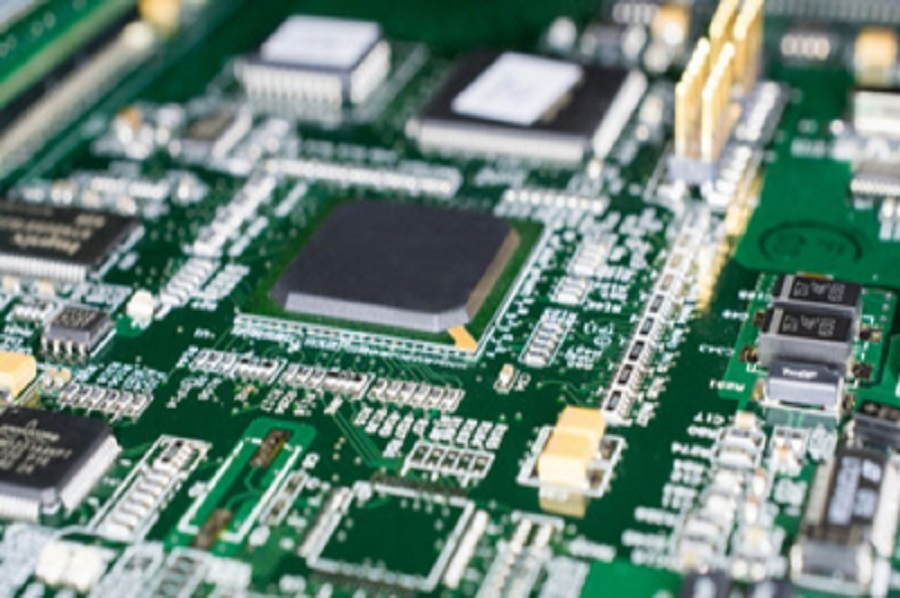
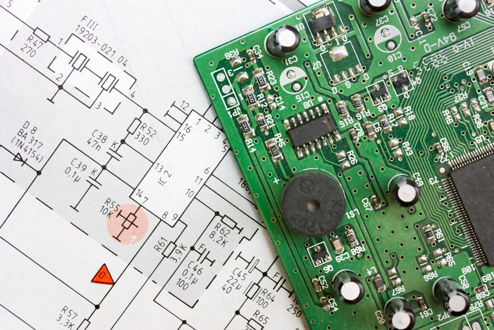
Electrical Circuit board consists of a substrate (typically made of fibreglass or other insulating materials) with thin conductive pathways etched onto its surface. These pathways, known as traces, serve as the highways for electrical signals.
Various electronic components, like resistors, capacitors, and integrated circuits, are soldered onto the board, forming a network that processes and directs electrical currents. By carefully designing the layout and connections, engineers create circuits that execute specific functions, enabling your devices to function as intended.
In this article, we'll explore the fascinating world of circuit boards and demystify how do circuit boards work. So, get ready to dive into the inner workings of these technological marvels and discover the secrets behind your favourite gadgets.
Let's get started!
The Basics of Circuit Boards
If you frequently use electronic devices, you may have wondered, 'How does a circuit board actually work?' Well, let's dive into the basics of electrical circuit boards.
What is a Circuit Board?
A circuit board, also known as a printed circuit board (PCB), is a flat board made of non-conductive material, such as fibreglass or plastic, with conductive pathways etched or printed onto it. These pathways, called traces, connect the electronic components on the board, such as resistors, capacitors, and integrated circuits.
The electrical circuit board acts as a platform for these components to communicate and work together to perform specific functions. When you power on a device, electricity flows through the traces, allowing the components to send and receive signals, process data, and ultimately make your electronic device function as intended.
Components of a Circuit Board
|
Component |
Function |
|
Integrated Circuit |
Contains transistors, resistors, and capacitors to perform specific functions. |
|
Connector |
Allows different parts of the circuit board to connect with external devices. |
|
Capacitor |
Stores and releases electrical energy. |
|
Resistor |
Regulates the flow of current. |
|
Diode |
Allows current to flow in one direction. |
|
Power Source |
Provides the necessary energy (e.g., batteries or power supplies) to run the circuit board. |
To understand how do circuit boards work, let's now explore the components that make up these essential electronic platforms.
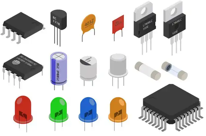
Electrical Circuit boards consist of various components that work together to ensure the smooth functioning of electronic devices. The most crucial component is the integrated circuit (IC), also known as a microchip. This small chip contains transistors, resistors, and capacitors that perform specific functions.
Another essential component is the connector, which allows different parts of the circuit board to connect with external devices. Capacitors store and release electrical energy, while resistors regulate the flow of current. Diodes, on the other hand, allow the current to flow in one direction.
Finally, there are the power sources, such as batteries or power supplies, which provide the necessary energy to run the circuit board.
Understanding these components is crucial in comprehending how do circuit boards work.
The Role of Conductive Pathways
Conductive pathways play a crucial role in ensuring the smooth flow of electrical signals within a circuit board. These pathways, often made of copper, act as the channels through which electricity travels. By connecting various components on the board, they create a complete circuit that allows current to flow from one point to another.
The pathways are carefully designed to be efficient and reliable, with the aim of minimising resistance and maximising conductivity. They're typically etched onto the surface of the board, forming an intricate network of interconnected lines. This network allows for the precise routing of signals, ensuring that they reach the intended destinations without interference or distortion.
Without these pathways, the electrical circuit board would be unable to function properly, making them an essential element in the overall operation of electronic devices.
Understanding Circuit Board Connections
Now, let's delve into how you can understand the connections on a circuit board.
Circuit board connections are made using various methods, such as through-hole technology or surface mount technology.
Through-hole technology involves inserting components through pre-drilled holes on the board and soldering them to the copper pads on the opposite side.
Surface mount technology, on the other hand, involves attaching components directly to the surface of the board using solder paste and a reflow process.
It's important to understand the connections on a circuit board because they determine how signals and power flow between components.
How Circuit Boards Power Our Devices
By connecting components and facilitating the flow of signals and power, electrical circuit boards play a crucial role in powering our devices. When you turn on your smartphone or computer, the circuit board inside it enables the electricity to flow through various paths, providing power to every component.
The main power source, such as a battery or wall outlet, supplies electrical energy to the circuit board. The board then distributes this power to different areas of the device, such as the processor, memory, and display. It ensures that the right amount of voltage and current is delivered to each component, preventing damage and ensuring proper functioning.
Additionally, circuit boards often include voltage regulators and protection circuits to safeguard the device from power surges or short circuits. Without circuit boards, our devices would be unable to receive the necessary power to operate efficiently.
What Are the Different Types of Circuit Boards and Their Specific Uses?
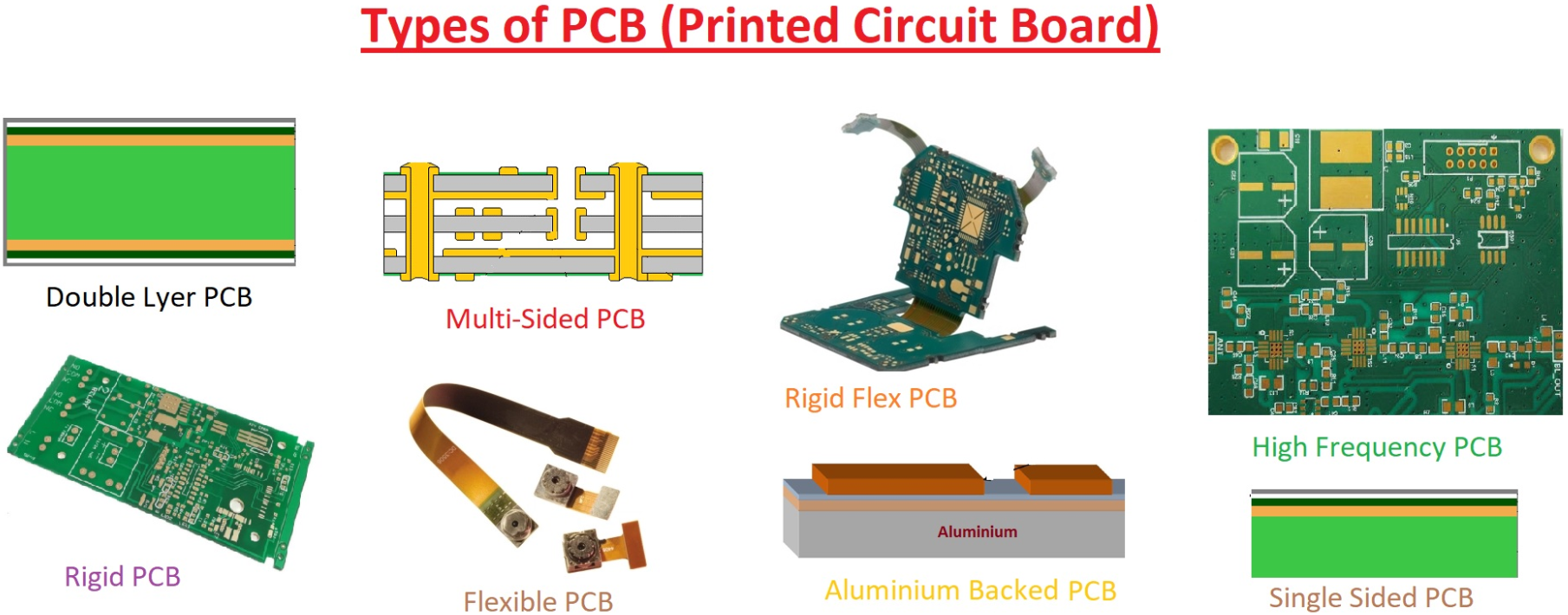
There are different types of circuit boards with specific uses. They allow electronic devices to function properly by connecting components and providing pathways for electrical currents to flow.
Circuit boards are essential components in the design and manufacturing of electronic devices. They come in various sizes and shapes, depending on the complexity and purpose of the device they are used in.
For example, a simple electronic toy may have a small circuit board with basic components, while a complex computer or smartphone will have a much larger and more intricate electrical circuit board.
The main purpose of a circuit board is to provide a platform for connecting different electronic components together. These components can include resistors, capacitors, transistors, and integrated circuits.
The circuit board acts as a foundation for these components, allowing them to be securely attached and creating a pathway for electrical currents to flow between them.
In addition to connecting components, circuit boards also provide pathways for electrical signals to travel. The layout of the circuit board is carefully designed to ensure that signals flow smoothly and efficiently between different parts of the device.
This is achieved through the use of conductive traces, which are thin strips of copper or other conductive materials that connect the various components on the board.
There are also specialised types of electrical circuit boards that serve specific purposes. For example, printed circuit boards (PCBs) are a common type that is used in many electronic devices.
These boards are made by printing a circuit design onto a flat surface, usually made of fiberglass or another non-conductive material. This allows for precise and efficient manufacturing of complex circuitry.
How Do You Make a Circuit Board
Whether you are a hobbyist or a professional, understanding how to make a circuit board can be a valuable skill. So, let's dive in and explore the fascinating world of how do circuit boards work and how to make it .
1. Understanding the Circuit Design
Drawing the Schematic
The first step in making a circuit board is to design the schematic. This schematic serves as a detailed description of all the parts involved and the connections between them. You can draw the schematic on graph paper or utilize simulation programs such as MultiSim or Eagle CAD. The goal is to create a clear and easy-to-follow representation of your circuit.
Prototyping on a Breadboard
If you are not using a simulation program, it is advisable to assemble and test one or more prototypes of your circuit on a breadboard. Breadboards are user-friendly tools that allow you to experiment and view real-time results without soldering or making permanent etches. This step helps ensure that your circuit functions as intended before moving on to the circuit board creation.
Utilizing Simulation Programs
Simulation programs like MultiSim or Eagle CAD provide a virtual environment for designing and testing circuits. These programs offer a range of features, including libraries of electronic components, circuit simulation, and real-time analysis. By utilizing these programs, you can create and test your circuit design digitally before moving on to the physical circuit board.
2. Preparing the Circuit Board
Choosing the Right Board
Before transferring your circuit design to a physical board, you need to choose the appropriate type of circuit board. Circuit boards are typically made of copper-coated insulator material and come in various sizes. A common size is 3.5 inches by 5 inches. Select a board that suits your project's requirements and ensure it has a copper layer on one side.
Printing the Design
Once you have finalized your circuit design, you can print it using a computer program or draw it by hand. If you choose to print it, ensure that you use glossy paper, such as those found in magazines or separate glossy paper. The quality of the print will affect the accuracy of transferring the design to the circuit board.
Transferring the Design to the Board
To transfer the design from the printed paper to the circuit board, you will need an electric iron. Cut out the design carefully and position it on the board. Place the hot iron directly on top of the circuit board for about 45 seconds. The heat will transfer the ink from the paper to the copper surface of the board. After heating, remove the paper, leaving the ink on the board.
3. Etching the Circuit Board
Heating the Electric Iron
Before etching the circuit board, it is crucial to heat the electric iron. However, it is essential to note that the iron should not be heated above 115°F (46°C) to prevent the release of toxic fumes. This process should be conducted in a well-ventilated space with proper safety precautions.
Applying the Design to the Board
After transferring the design to the circuit board, it is time to etch the board. Using plastic tongs, place the circuit board face down on the risers in a tray. The exposed copper will slowly dissolve as the etching process takes place, leaving behind the desired circuit pattern. The time required for etching depends on the size of the board, typically ranging from 5 to 20 minutes.
Washing the Paper Out
Once the etching process is complete, it is necessary to wash the paper off the circuit board. Carefully rinse the board, ensuring that the black ink is firmly stuck to the copper. This step reveals the copper traces that form the circuit. Take caution not to damage the traces while washing off the paper.
4. Designing the Circuit
Drawing the Circuit with a Sharpie
After etching the board, you need to draw out the circuit design using a Sharpie or another indelible marker. It is important to note that drawing complex circuit designs by hand can be challenging, especially when dealing with intricate components. However, for simple circuits like an LED and a battery, it can be feasible. Ensure that the copper traces are dissolved before the ink and that there are no thin patches in the ink exposing the copper.
Considering Copper Gaps
When drawing the circuit on the board, it is crucial to keep in mind that copper cannot be present between components that need to be connected. For example, when connecting an LED, there must be a gap in the copper between the positive and negative points to allow the electricity to flow through the LED. Follow the laws of electricity to ensure proper circuit connectivity.
Ensuring Proper Connectivity
All circuits must end at either a negative or ground point; otherwise, no current will flow. It is essential to create thin lines for the circuit connections but lay the ink on thick to ensure that the copper is dissolved before the ink. Avoid thin patches in the ink that expose the copper, as this can lead to improper connectivity.
5. Etching the Board
Temperature and Ventilation Considerations
During the etching process, it is crucial to maintain a temperature below 115°F (46°C) to prevent the release of toxic fumes. Additionally, the etching process should be conducted in a well-ventilated space to ensure the safe disposal of any fumes that may be generated.
Placing the Board in a Tray
To etch the board, place it face down on the risers in a tray. The exposed copper will slowly dissolve and drop off the board, leaving behind the desired circuit pattern. The timing of the etching process depends on the size of the board and can range from 5 to 20 minutes. Use plastic tongs to agitate the board and tray if faster etching is required.
Agitating the Board for Faster Etching
If you need to speed up the etching process, you can agitate the board and tray. Gently move the board back and forth in the tray using plastic tongs. This agitation helps the etching chemical to reach all areas of the board, resulting in faster and more uniform etching.
6. Drilling and Soldering
Preparing for Drilling
After etching the board and achieving the desired circuit pattern, it is time to prepare for drilling. Gather a handheld drill or a drill press, along with suitable drill bits. Before drilling, ensure that you wear a protective mask to avoid inhaling any copper dust, as it can be toxic.
Understanding Through Hole and SMD Components
When working with circuit boards, it is important to differentiate between through hole and surface mount devices (SMDs). Through hole components have long legs that enter the board from the opposite side of the copper. On the other hand, SMDs are surface-mounted and do not require drilling. It is crucial to drill holes in the board for through hole components to enable proper soldering.
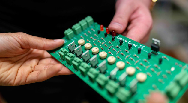
Soldering the Components
To assemble the circuit, you will need to solder the components onto the circuit board. Gently bend the legs of the through hole components against the underside of the board to hold them in place. Ensure that components with polarity are correctly aligned with the corresponding positive and negative points. Double-check the location of all parts before soldering to avoid any mistakes. A soldering iron and solder are essential tools for this process.
7. Troubleshooting and Testing
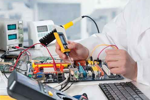
Using a Multimeter
After soldering the components, it is crucial to test the circuit for any connection problems. A multimeter can be a handy tool to diagnose and troubleshoot circuit issues. By measuring voltage, current, and resistance at different points in the circuit, you can identify any faulty connections or components.
Making Minor Repairs with a Desoldering Gun
If you encounter any minor issues or need to make changes to the circuit, a desoldering gun can be a useful tool. It allows you to remove soldered components without damaging the board or other components. This tool comes in handy for making repairs or modifications during the testing phase.
Diagnosing Connection Problems
If you experience connection problems or the circuit is not functioning as expected, it is essential to analyze the circuit carefully. Check each component's placement and orientation, ensuring they are correctly positioned and soldered. Trace the circuit's path visually and use a multimeter to identify any potential connection problems.
Conclusion
So there you have it, electrical circuit boards are the backbone of our electronic devices. They work by connecting various components through conductive pathways, allowing electricity to flow and power our devices.
Whether it's a smartphone, a computer, or any other electronic gadget, circuit boards play a crucial role in making them function. Understanding how do circuit boards work can give us a deeper appreciation for the technology that surrounds us every day.
FAQs:
1. How Are Circuit Boards Manufactured and What Materials Are Used?
Answer: To understand how do circuit boards work, you need to know how they're manufactured and what materials are used.
Circuit boards are made by layering materials like fiberglass and copper, creating pathways for electrical currents to flow.
2. What Are Some Common Issues or Problems That Can Occur With Circuit Boards?
Answer: Some common issues or problems that can occur with circuit boards include:
- Short circuits
- Loose connections
- Component failure
- Overheating
These problems can affect the functionality and performance of the circuit board.
3. Are There Any Safety Precautions or Regulations Associated With Circuit Boards?
Answer: There are safety precautions and regulations associated with circuit boards.
It's important to follow proper handling procedures and wear protective gear to prevent electrical shock or damage to the board.
4. How Do Circuit Boards Work to the Advancement of Technology?
Answer: Circuit boards contribute to technology advancement by providing a platform for electronic components to connect and communicate. They enable the creation of complex circuits that power devices and systems. This, in turn, makes our lives more efficient and connected.


