Minimum Bending Radius Calculation for Flex PCB
When people thought technology had reached its peak, humans invented the circuit board. Circuit boards allowed electricity use in devices and have been a part of all scientific research and technological advances ever since.
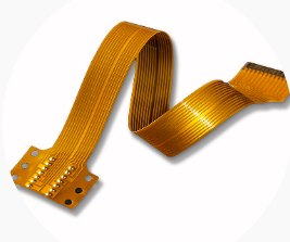
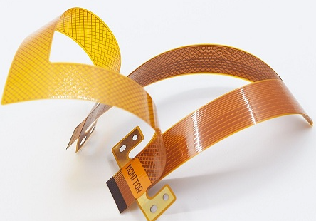
The flex PCB has become the most commonly used circuit in recent years. Flexible circuits allow themselves to bent, allowing more application. The vital thing to know is how much can a flex circuit bend.
We need the minimum bending radius calculations for flex PCB to know that.
This article will go through the minimum bending radius calculations for flex PCB and how to calculate them. Before that, we need to know why the bending radius is essential for a flex PCB.
The Importance of Flex PCB Bending Radius
The bending radius of the flexible circuit represents the minimum degree to which one can bend the flex circuit without damaging it. The smaller the bending radius, the greater the flexibility.
Due to the minimum bending radius of the Flex Printed Circuit (FPC), the flex PCB can be manipulated and bent to fit inside electrical designs. This allows for a wide range of applications for the flex PCB. There are many benefits of the bending radius, some of which are mentioned below:
Flexibility
Flexibility is the most significant selling point of the flex PCB. The minimum bending radius, as mentioned before, is responsible for its flexibility. The ability to be bent allows freedom of creativity and design. This has allowed flex PCB to be used in smaller devices and the production of complex designs without the need for multiple circuit boards.
Less Weight
To bend, the circuit board needs to be lightweight and thin. The smaller the bending radius, the lesser the weight required. The decrease in weight increases shock absorption and reliability and allows the circuit to be used in lightweight products.
Increased Connectivity
Flex PCBs are used in dynamic flex circuits mainly because of their ability to bend, which allows for an indefinite number of cycles, increasing connectivity in electrical components. Multi-layered flex PCB allows for greater connections without compromising on weight and flexibility.
Why Should You Calculate the Flex PCB Minimum Bending Radius
The minimum bending radius is necessary because it tells us how much the flex PCB can bend without compromising functionality. This limits how much strain can be subjected to flex PCBs.
If bent too much, the internal bend faces compressive forces, and the external bend faces tensile forces, damaging the flex PCB. This puts undue strain on the flex PCB and leads to damages, malfunctioning, and decreased life span. Knowing how much you can bend the flex PCB is important for long-term enhanced performance.
The minimum bend radius depends on the three types of flex PCB design standards:
Stable Flex PCB
The stable flex PCB involves a flex layer bent into shape to fit into a design. The bend is done at the beginning of the installation. For one or two layers, the minimum bend radius is 6X, and for multiple layers, the minimum bend radius is 12X.
Dynamic Flex PCB
Dynamic flex PCB involves a flex layer that has been done through repetitive bending, so the layers are limited to two. The minimum bending radius is around 100X.
One Time Crease
Flex PCB based on the one-time crease design does not put relevance onto the minimum bend radius. This is because the flex layers are creased and installed into the design.
How to Calculate Flex PCB Minimum Bending Radius
The minimum bending radius is calculated as a product of the thicking of the application and the ratio of the height of the flexible part and bending radius. The equation used to calculate the minimum bending radius can be written as:
Minimum bending radius = (r/h of design standard) x application thickness.
Where r is the bending ratio and h is the overall height of the flexible part.
The ratios (r/h) for different layers of stable and dynamic design standards are mentioned in the table below:
|
Layer |
Stable Design |
Dynamic Design |
|
Single Layer |
10:1 |
100:1 |
|
Double Layer |
10:1 |
150:1 |
|
Multi-layer |
20:1 |
Not recommended |
Using these ratios, we can calculate the minimum bending radius of a flexible circuit, given that we know the thickness of the circuit.
For example, to find the minimum bending radius of a double-layered dynamic design with a thickness of 190 µm, we can calculate it by:
Minimum bending radius = (r/h of design standard) x application thickness
= (150:1) x (190 x 10-6)
= 29 mm
Hence, the flex circuit has a minimum bending radius of 29 millimetres.
Minimum Bending Radius Calculation for Flex PCB
Some calculations of the minimum bend radius of flex PCBs with assumed thickness are mentioned in the table below:
|
1 layer, e.g., 90 µm thickness |
Stable |
Semi-Dynamic |
Dynamic |
|
Minimum Ratio (r/h) |
10: 1 |
20: 1 |
100: 1 |
|
Minimum Bending Radius |
0.9 mm |
1.8 mm |
9 mm |
|
2 layer, e.g., 190 µm thickness |
Stable |
Semi-Dynamic |
Dynamic |
|
Minimum Ratio (r/h) |
10: 1 |
20: 1 |
150: 1 |
|
Minimum Bending Radius |
1.9 mm |
3.8 mm |
28 mm |
|
4 layer, e.g., 290 µm thickness |
Stable |
Semi-Dynamic |
Dynamic |
|
Minimum Ratio (r/h) |
20: 1 |
50: 1 |
Not recommended |
|
Minimum Bending Radius |
5.8 mm |
15 mm |
Not recommended |
Conclusion
The minimum bend radius is an essential feature of a flexible circuit responsible for most of its properties. We need to know how to calculate the minimum bending radius and the minimum bending radius calculations of some flex PCB designs.
There are many ways the minimum bending radius can affect the flex PCB. Without knowing the minimum bend radius, an extra force could be exerted on the flex PCB, resulting in damage or decreased circuit life span. To avoid that, calculations on minimum bend radius are continuously being made as each flex PCB is designed.


