Rigid-flex PCBs technical specification and flex bending radius Calculation
Our flex and rigid flex circuits solutions are custom designed for many top tier OEMs. Manufactured with dependable reliability, our flexible circuits are built to withstand the rigors of aerospace, medical, and military applications. As a high reliability replacement for wire and wire harness assemblies, flex circuits provide a significant cost savings with no reduction in performance.
Cost Effective Flex & rigid flex circuits
When it comes to our flex and rigid flex circuits products, we offer a variety of cost effective solutions and capabilities that include single or double sided circuitry to higher technology multilayer designs up to 6 layers. From selecting the best functional configuration, to choosing the proper connectors or components, we will help you meet or exceed all your applications requirements.
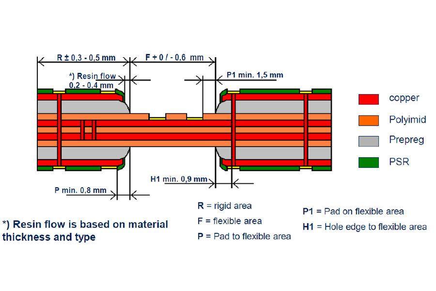
Tolerances for interface flexible and rigid area.

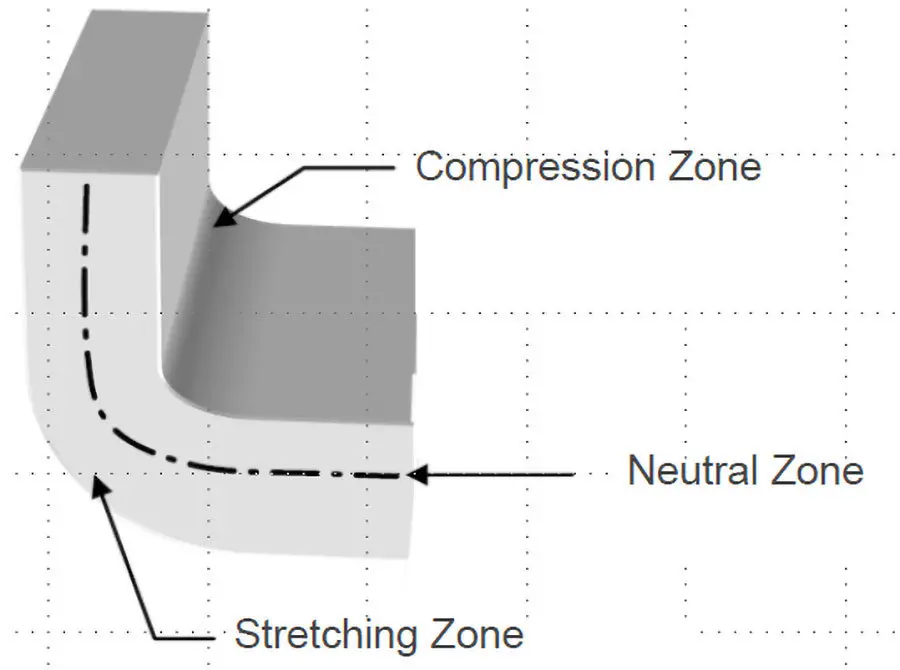
What determines the flexibility and thus the bending radius of a flexible or rigid flex circuit?
- The type of materials used
- The thickness of the flex part of the PCB
Rule of thumb for calculating the bending radius:
- 1-Layer, Rigid-Flex-PCB: = r(min) = 6 x h
- 2-Layer, Rigid-Flex-PCB: = r(min) = 10 x h
- Multilayer, Rigid-Flex-PCB: = r(min) = (10-15) x h
- Strong dynamic loaded rigid-flex PCB: = r(min) = 25 x h
“h” is the thickness of the flexible PCB
Calculate 150µm for a 1-layer, and 200µm for a 2-layer printed circuit board. It guarantees are already included.
Example:
A 2-Layer rigid-flex PCB is 200 microns thick. From the formula above: 10 x 200 microns = 2000μm = 2mm.
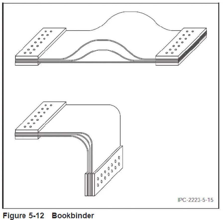
Bookbinder bending:
Differential Lengths (Multilayer and Rigid Flex circuits)
The bookbinder design of an unbonded flex area can be used in regions where a sharp bend (radius to thickness ratios <6) is required. This technique uses progressive lengths in the flex area (see Figure 5-12) and is costly to manufacture because of tooling complexity, processing difficulties, and reduced yields. Corresponding calculation See: IPC-2223
Bookbinder bending:
Differential Lengths (Multilayer and Rigid Flex circuits)
To work out the additional length needed for each flexible circuit layer above the innermost layer, use the calculation given by IPC-2223:
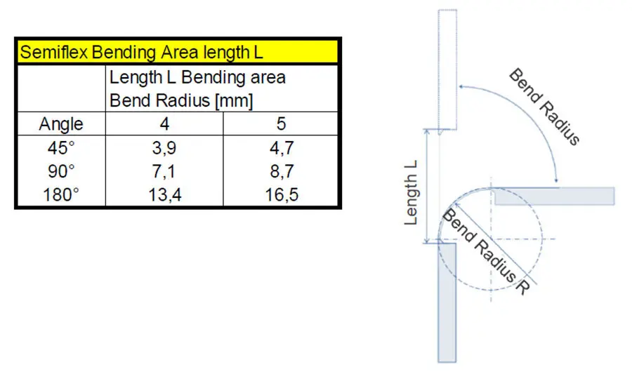
Rigid flex circuits Bend-Radius:
Calculation of the necessary length L of Bending range: L = angle x radius R x Pi / 180 °+ 2 x 0.4 mm)
Rigid flex pcb Layout guidelines
From the differences mentioned above, for the layout and use of rigid flex circuits, the following can be deduced:
- For single-sided flexible circuits, the bending radius is approximately 6 x the thickness
of the flexible material, and for double-sided circuits it is approx. 12 x the thickness. - Choose track widths and spacing in the flexible region to be as large as possible (> 150 µm)
- The flexible region should have parallel tracks which are the same width, with the same leakage resistance, and which run at 90° to the bend line
- Tracks should extend at least 1 mm into the rigid region
- On flexible layers, include hatched copper areas which are as large as possible
- The tracks on double-sided, flexible parts should be symmetrically offset
- Holes should be at least 2 mm away from a flexible part
- Choose solder surfaces to be as large as possible, the diameter of solder eye pads should be at least twice the diameter of the hole.
- Solder must not come closer than 1 mm to the flexible area
- Add about 1 mm all round to the dimensions of openings in non photostructured covering films
- To be able to assemble the components on a board, to solder & check them, a stiff frame with defined breaking points should be used. Blanks can contain single or multiple boards.
- Always use smooth (round) milling transitions to the connected parts of the circuit


