Applying DFM Analysis to Flexible PCB Design
Designing or manufacturing a cable or flex PCB can be challenging, but with the help of Design for Manufacturing (DFM), things become more accessible. The job of the design engineer is to come up with easily manufactured designs. In a complex PCB design, it is difficult to determine how variations affect all aspects of the design in a high-level manner, which affects overall design quality.
Design for Manufacturing (DFM) is a methodology, and set of tools engineers use to improve development processes in product manufacturing. A primary benefit of using a DFM methodology is that it turns the making of products into a data-driven process, where one can test, adapt and forecast a product’s performance at each stage of development based on objective and measurable data generated by the use of DFM techniques.
Design for manufacturability (DFM) analysis is often neglected in the design process, even though it provides a thorough insight into evaluating the real-time capabilities of a product. This guide looks at why DFM is important and then shows you how you can apply DFM analysis to your next flexible PCB design.
DFM Analysis for Flexible PCBs
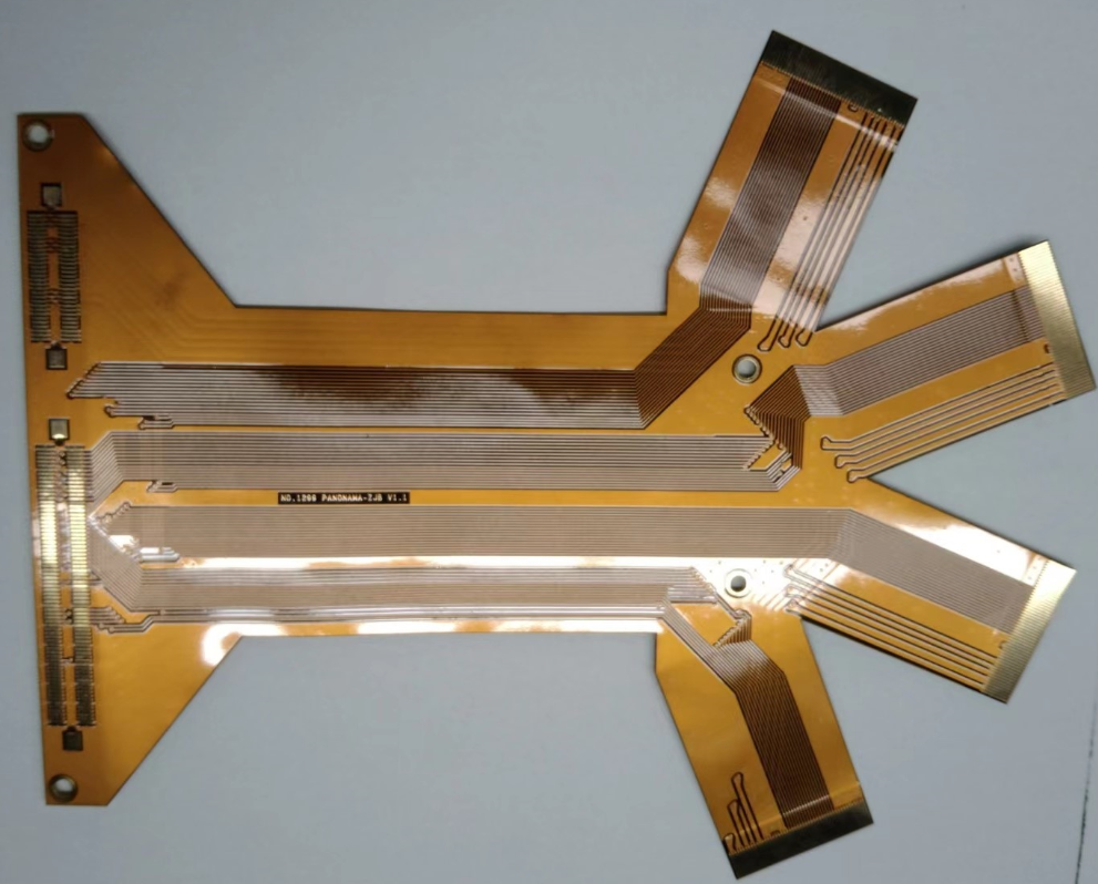
Flexible PCBs (FPCBs) have potential reliability issues caused by the flexible properties of the material itself. DFM techniques are adapted for these circuits and can help reduce costs and improve flexibility.
DFM analysis for Flexible PCBs is a critical process of designing a component for high performance, reliability, and safety. It requires a thorough understanding of the component and system requirements and the manufacturing process.
The following steps are followed in the DFM analysis for Flexible PCBs:
Determine the Requirements
The first step is determining what requirements must be met by the end product. This includes determining how much pressure will be applied to the product, what factors affect its flexibility and how much weight it needs to support. Engineers can then use this information to determine how flexible their products will need to meet these requirements.
Perform Failure Mode Effects Analysis (FMEA)
Failure mode effects analysis (FMEA) is used to identify potential failures that may occur during the production or operation of a product. It helps you find out what could go wrong with your product and how much impact it will have on your business if it fails at some point during its lifetime. FMEAs are done during various stages of development, including concept generation, product/process design, and manufacturing process engineering/design validation activities. It is helpful as they provide an insight into potential failure modes so that they can be eliminated from the system or controlled/mitigated to acceptable levels.
Perform Stress Analysis
Stress analysis helps determine how much stress a material can withstand before failure occurs. This is done by putting together all the materials and components of a product and testing them under different conditions such as temperature, pressure, vibration, and other factors that might affect them over time. Stress analysis not only helps you determine whether your product meets its requirements but also helps you predict if there are likely to be any problems in the future based on the stresses applied to it over time.
The stress analysis includes:
Thermal Analysis
Thermal analysis is the most critical step of DFM analysis for flexible PCBs. The thermal analysis determines the thermal resistance of all the components on the board, and then you have to adjust your design accordingly to make sure that it will be able to operate within its operating range without overheating.
The temperature distribution within the product should be determined for different environmental conditions. The maximum temperature reached by any component should be specified along with its location in the PCB design.
Electrical Analysis
Conduct electrical analysis to determine whether there is any electrical interference from external sources or internal components due to movement of the product or any other factors such as heat generation from motors etc.,
It is crucial that no electrical interference occurs during the operation of any part of the product because this may lead to circuits malfunctioning and damage to sensitive parts like microelectronics and microprocessors etc. For example, if a motor generates an electromagnetic field while working, it may interfere with other electronic devices nearby, which are connected via cables or wires and hence depend upon radio frequency signals. In such cases, use shielding techniques to prevent interference.
Mechanical Analysis
Mechanical analysis is also an essential step in DFM analysis for flexible PCBs because it determines what kind of mechanical support structures are needed on the board to ensure that it will work properly under different conditions such as temperature variation, shock, and vibration.
Mechanical analysis determines whether or not your mechanical design, such as bending stress, can withstand flexing and bend under normal use conditions. It also determines if there are any weak spots in your design that could cause failure due to mechanical stress, such as cracking. Moreover, the maximum deflection should be specified at each joint.
Estimate Reliability
In the context of PCBs, reliability is the probability that a system will perform its required functions under stated conditions for a specified period. It estimates the likelihood that a product will perform its required functions without any failures during its useful life. If the product meets all requirements for performance and quality but does not have sufficient reliability, then it cannot be used in many situations where failure means a catastrophic loss of life and property.
In general terms, reliability engineering is concerned with identifying, quantifying, and controlling all factors that can cause equipment failure or loss of service. It uses failure mode effects analysis (FMEA) and fault tree analysis (FTA).
Estimate MTBF (Mean Time Between Failures)
MTBF estimates are often used as part of reliability engineering to predict the failure rate of a system or component. Reliability engineers use this data to determine if a system design is adequate for its intended use and whether any improvements can be made to reduce the failure rate further. For example, if you know your system has an MTBF of 100 hours, but after testing, it fails after just 50 hours on average, then you know there is room for improvement in your design and manufacturing process.
Summing Up
DFM plays a critical role in the development of flexible PCBs. And since the design for manufacturing focuses on both production and design, it also makes sense to apply DFM analysis to flexible PCBs. By taking DFM analysis into account from the beginning, designers can ensure that their PCBs will be easier to manufacture, helping them reduce costs, adhere to deadlines, and achieve higher yields of completed boards at the end of production.
If you want to learn more about flexible PCBs and need a high-quality PCB manufacturer, check out Hemeixin.


